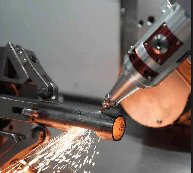
In my 15 years as a senior laser equipment engineer, I’ve walked into hundreds of fabrication shops where the sound of angle grinders and tumbling machines drowns out the hum of production. While a modern fiber laser tube cutting machine promises “net shape” production, the reality on the shop floor often involves fighting persistent defects that eat into profit margins.
Every cut defect is not just an annoyance; it is a “fingerprint” left by the laser beam. If you know how to read that fingerprint, you can diagnose a process imbalance without even looking at the control screen. This article provides a systematic framework to identify laser tube cutting machine problems, offering technical root causes and actionable tube cutting troubleshooting strategies to help factory owners and engineers achieve repeatable, high-quality results.
1. Dross and Slag Adhesion (The “Icicle” Burr)
Problem Description:
Dross, or slag, is the unwanted, re-solidified metal that sticks to the bottom edge of the tube wall. It appears as hard, rounded beads that look like melted candle wax.
Possible Causes:
This is typically “Low-Speed Dross” caused by overheating. When the cutting speed is too slow, the laser puts excessive heat into the material, creating a thick, viscous melt film that the assist gas cannot fully eject.
Practical Solutions:
- Increase Cutting Speed: Raise the feed rate in 10% increments to restore thermal balance.
- Check Gas Pressure: If cutting stainless steel with nitrogen, ensure pressure is sufficient — typically 20–25 Bar depending on wall thickness and laser power — to forcefully eject the melt pool.
- Nozzle Inspection: A nicked or dirty nozzle can cause turbulent gas flow, preventing clean ejection.
2. Sharp, Angled Burrs (High-Speed Dross)
Problem Description:
Unlike rounded dross, these are small, sharp, jagged trails that angle backwards relative to the cutting direction.
Possible Causes:
This is a sign of under-penetration. The laser is moving too fast for the beam to fully liquefy the bottom of the tube wall, forcing the assist gas to push semi-solid material that clings to the edge.
Practical Solutions:
- Decrease Speed: Reduce cutting speed in 5% increments until the burrs disappear.
- Adjust Focal Position: Lower the focus (more negative) to increase energy density at the bottom exit of the cut.
3. Tube Clamping Instability and Positional Shift
Problem Description:
The workpiece shifts or vibrates during rotation, leading to cutting accuracy issues, such as square holes that don’t align on opposite sides of the tube.
Possible Causes:
The root cause is often “non-repeatable clamping behavior”. This can be due to unbalanced pneumatic jaw pairs, worn jaw faces, or a drop in pneumatic pressure below the manufacturer’s specified operating range, typically 0.4–0.6 MPa.
Practical Solutions:
- Verify B-Axis Concentricity: Use a dial indicator to check runout. A target of ≤0.05mm is standard for precision tube fabrication.
- Lubrication and Cleaning: Swarf and iron filings accumulate in the chuck’s guide rods. Clean and lubricate with lithium-based grease every shift.
- Adaptive Support: For thin-walled tubes, use anti-deformation supports or reduce clamping force to avoid crushing the profile.
4. Striations and Drag Lines (The “Backward Lag”)
Problem Description:
The cut face shows deep, rough lines that angle sharply backward instead of being vertical and shallow.
Possible Causes:
The bottom of the laser beam is lagging behind the top due to excessive speed or insufficient gas pressure.
Practical Solutions:
- Match Power to Speed: If striations are severe, slow down until the lines become vertical.
- Check Assist Gas: Ensure the gas path is smooth and free of leaks. For thick steel, avoid overly high oxygen pressure which can create turbulent “chewed” edges.
5. Thermal Focus Shift (Drifting Quality)
Problem Description:
The machine starts the shift with perfect cuts, but after 30 minutes, the edges become rough, tapered, or the laser fails to cut through.
Possible Causes:
This is the classic sign of Thermal Lensing. Dust or smoke on the protective window absorbs laser energy, causing the lens to heat up and warp, which shifts the focal point upward.
Practical Solutions:
- Clean Optics: Inspect the protective window daily. Use only lint-free cotton buds and denatured alcohol.
- Chiller Maintenance: Ensure the water chiller maintains a stable temperature of 22°C ±1°C. A fluctuation greater than ±2°C can accelerate thermal lensing and cause unpredictable focus drift.
6. Internal Spatter and Slag Inside the Tube
Problem Description:
Molten metal spatter falls onto the opposite inner wall of the tube, creating rough deposits that interfere with assembly or fluid transport.
Possible Causes:
The primary driver is excessive energy during the piercing phase. A high-energy pierce point generates a large initial melt pool that splashes onto the inner wall before the cutting cycle begins.
Inadequate assist gas flow during piercing compounds the problem.
Practical Solutions:
- Optimize Pierce Parameters: Reduce peak power and extend pierce time during the piercing phase to minimize the initial melt explosion. This is the most effective first step.
- Increase Assist Gas Pressure at Pierce: Temporarily boosting gas pressure during the pierce cycle helps eject molten material downward rather than allowing it to splash onto the inner wall.
- Relocate the Pierce Point: Where the part geometry allows, move the pierce point to a scrap zone or a tab area rather than piercing directly on the finished edge.
Note: Anti-spatter fluids applied to the inner wall can provide a barrier in some applications, but use with caution if the tube will be welded afterward, as residue can compromise weld quality.
7. Corner Overburning (Corner Blowout)
Problem Description:
As the laser head turns a 90-degree corner, the material melts away or “blows out,” leaving a rounded or notched defect.
Possible Causes:
The cutting head slows down at the corner, but if the laser power remains constant, the material absorbs too much energy (thermal runaway).
Practical Solutions:
- Pulse Modulation: Use CNC features that automatically reduce laser power and frequency at inflection points based on speed.
- Sharp Corner Loops: Implement “Sharp Corner Ring Cutting” paths that move the laser in a small loop outside the part to allow for cooling.
8. Tapered or Beveled Edges (The V-Shape)
Problem Description:
The cut edge is not square; for example, the top of the kerf is wider than the bottom, resulting in a 100mm part measuring 100.5mm at the base.
Possible Causes:
Incorrect focal position is the primary culprit. If the focus is too high (too positive), the beam diverges as it travels through the material, producing a wider kerf at the top than the bottom.
Practical Solutions:
- Calibrate Focus: For stainless steel with nitrogen, a negative focal offset is generally recommended as a starting point. The optimal value depends on wall thickness — thinner walls (1–2mm) typically require a shallower offset around -1mm, while thicker walls (6–8mm) may need -3mm or beyond. Always verify against a test cut before production.
- Beam Centering: Perform a centering tape test (also called a nozzle alignment test) to ensure the beam passes exactly through the center of the nozzle.
9. Oxidation and Discoloration (Yellowing)
Problem Description:
The cut edge of a stainless steel tube appears yellow, straw-colored, or black despite using nitrogen.
Possible Causes:
This indicates insufficient gas purity or a leak in the supply line allowing oxygen to mix with the nitrogen.
Practical Solutions:
- Verify Gas Purity: Use nitrogen with 99.995% purity or higher for a bright, oxide-free finish.
- Increase Gas Delay: Increase the “gas lead” time to ensure the gas line is purged of air before the laser fires.
10. Discontinuous Kerf (Incomplete Cuts)
Problem Description:
The part is not fully separated, leaving “stitches” or gaps along the cutting path that require manual breaking.
Possible Causes:
While an unstable power supply is one possible cause, incomplete cuts more commonly result from one of three sources: degraded laser output consistency due to aging pump diodes inside the laser source; abnormal response from the capacitive height-sensing system causing the cutting head to momentarily lift away from the focal position; or an imbalance in the four core parameters — power, speed, focus, and assist gas pressure — for the specific wall thickness being cut.
Practical Solutions:
- Check the Height Sensor First: Clean the capacitive sensor and verify its response curve. An erratic height sensor is one of the most common and most overlooked causes of intermittent incomplete cuts.
- Inspect the Laser Source: If the machine has significant operating hours, consult your laser source manufacturer to evaluate pump diode performance. Output degradation is gradual and easy to miss.
- Voltage Stabilizer: If power supply instability is confirmed, install a dedicated voltage stabilizer to ensure the high-voltage power supply receives a clean signal.
- Rebalance Core Parameters: Verify that power, speed, focus, and assist gas pressure are properly optimized for the wall thickness in production.
Maintenance Tips to Prevent Fiber Laser Cutting Issues
Daily: Check nozzle for spatter and visually inspect the protective window for dust.
Weekly: Clean the chuck jaws and guide rails to prevent swarf buildup from affecting alignment.
Monthly: Inspect the water chiller filter and examine electrical connections for signs of overheating.
Quarterly: Perform a full B-axis concentricity check and re-tension the slider chains.
Conclusione
Stable, high-quality tube cutting is not achieved by chasing perfect parameters in isolation. It requires a deep understanding of how energy input, molten material behavior, and mechanical motion interact as a complete system. By using a systematic, process-oriented approach — rather than reactive trial-and-error — manufacturers can significantly reduce secondary grinding operations and increase production reliability.
If you are consistently fighting ugly edges or tube cutting troubleshooting issues, it may be time for a professional application review. Feel free to explore our Tube Laser Cutting Machine Product Page or contact our engineering team for specialized support.