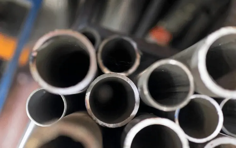
Laser cutting has become the default choice for high-precision metal fabrication. Whether you’re specifying parts for a production run or evaluating supplier quotes, understanding the practical differences and process controls for laser cutting stainless steel versus carbon steel will save time, reduce rework, and improve part quality.
Choose the right laser family for the job
Two laser technologies dominate industry use: fiber lasers and CO₂ lasers. For most modern shops and for laser cutting stainless steel, fiber lasers are the workhorse — they deliver high electrical-to-optical efficiency, tighter spots and lower operating cost for thin to mid-thickness sheets. CO₂ lasers can still be useful for very thick plates or when specific kerf profiles are required, but they usually mean higher maintenance and alignment needs.
When specifying equipment, match laser power to the expected thickness range and production rhythm (continuous, nested cutting, pierce frequency). Overspecifying power increases capital cost without guaranteed quality gains; underspecifying power increases pierce and cut failures.
Assist gas matters — surface finish vs speed
Assist gas choice is one of the simplest and most influential decisions:
- Stainless steel: Use high-purity nitrogen to produce a bright, oxide-free cut edge and preserve corrosion resistance. Nitrogen prevents oxidation during the melt-ejection process, keeping the cut surface suitable for many assemblies without additional passivation.
- Carbon (mild) steel: Oxygen is commonly used because it reacts exothermically with the metal, increasing cutting speed and allowing thicker sections to be cut with lower laser power. The tradeoff is an oxidized edge (visible dark scale) that may require post-cleaning.
Gas pressure and purity must be tuned by thickness. Low-pressure or contaminated gas will create dross and recuts; excessively high pressure can disturb the melt stream and widen kerf.
Nozzle, focus and piercing — small adjustments, big results
Three machine settings are repeatedly under-estimated:
- Nozzle diameter— select nozzle orifice proportional to sheet thickness. Smaller orifices concentrate gas flow for thin sheets; larger orifices help blow out molten material on thicker plates.
- Focus position— a slight negative focus (focus below the top surface) often improves cut edge quality for stainless by encouraging a stable melt pool and cleaner ejection; for some carbon steel applications a neutral or slightly positive focus gives faster penetration.
- Piercing strategy— use ramped, stepped or pulsed piercing depending on thickness and alloy. Controlled pierce reduces spatter and residual stress at the start hole.
Calibrate and save parameter sets for each material/thickness combination. This is where shops quickly gain repeatability.
Process window: balance power, speed, frequency
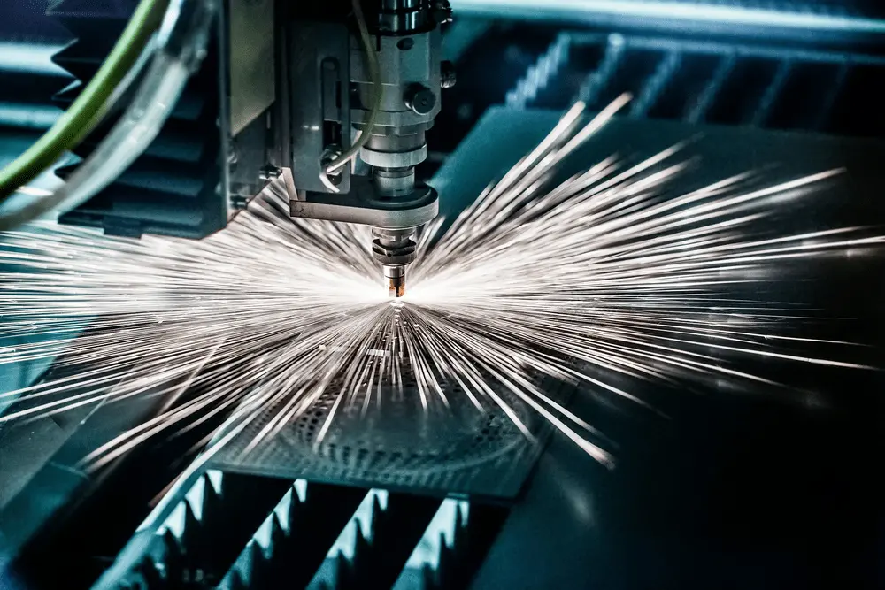
Optimizing the “process window” means finding the combination of laser power, traverse speed, and pulse or modulation frequency that yields a full-penetration cut with acceptable kerf and minimal dross.
A practical approach:
- Start with conservative pierce settings and reduce pierce time once cut is proven.
- Increase travel speed gradually until dross appears; then back off to the last good setting.
- For pulsed systems or where edge color matters, tune frequency and duty cycle to control melt dynamics.
Maintenance and alignment — non-sexy but essential
Regular preventive maintenance yields more uptime and fewer process surprises:
- Keep optics clean and aligned; even small contamination increases required power and worsens edge finish.
- Inspect and replace nozzles on schedule — small nozzle wear changes gas flow patterns.
- Monitor gas purity and pressure; track consumable batches so changes in edge quality can be traced to a root cause.
Post-processing and quality checks
Even with a tuned process, parts usually require some checks:
- Visual edge inspection for oxidation and dross.
- Dimensional checks (calipers, CMM for tight tolerances).
- For parts that must maintain corrosion resistance, consider passivation or electropolishing after cutting.
Practical reference table (quick-use)
| Material | Typicalthicknessband | Assistgas | Typicalnozzleorifice | Focusoffset(relativetosurface) |
| Stainless steel | 0.5 – 6 mm | Nitrogen (high purity) | 1.5 – 3.0 mm | Slight negative (–0.5 to –1.5 mm) |
| Stainless steel | 6 – 20 mm | Nitrogen (for color) / oxygen rarely | 3.0 – 4.0 mm | Slight negative to neutral |
| Carbon steel | 0.5 – 20 mm | Oxygen (for speed) | 2.0 – 4.0 mm | Neutral to slight positive |
(Use the table as a starting point — your machine, nozzle design and shop air/gas system will change the optimum.)
A short shop example
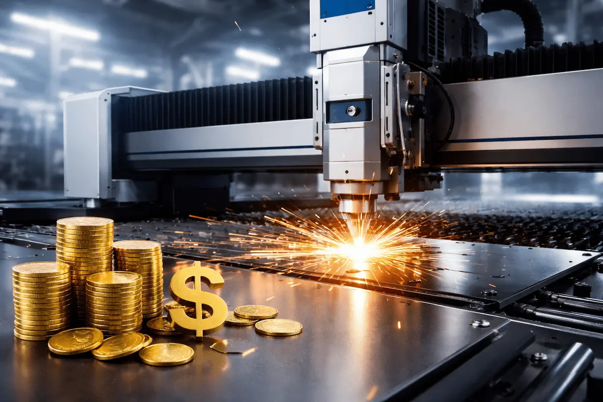
At Longxin Laser we often see shops reduce downstream finishing by 30–50% simply by switching from compressed air to instrument-grade nitrogen for stainless parts and by saving tuned recipes per job. The investment in a good gas system and disciplined parameter control almost always pays back in less rework and higher part acceptance rates.
Safety and environmental notes
Metal cutting creates fumes and particulates. Ensure proper extraction and filtration systems are installed and maintained. Guard operators with appropriate PPE and enforce permit procedures for large pierces and nesting runs.
Laser cutting is deceptively simple to start and richly nuanced to master. For procurement professionals, the best contracts combine clear material specs, agreed process windows, and measurable acceptance criteria (edge condition, dimensional tolerance, and surface treatment). For engineers and operators, incremental improvements — cleaner gas, better nozzles, saved recipe libraries and regular optics care — usually yield the biggest returns on yield and finish quality for laser cutting stainless steel and carbon steel projects.