1.Introduction
In the world of modern manufacturing, few terms are as deceptively simple—and yet as contextually rich—as fly cutting. To many CNC machinists, fly cutting refers to a classic face milling technique using a single-point cutter to achieve mirror-like flat surfaces on metal parts. But in the field of laser cutting, the same term takes on a very different meaning: an advanced, path-optimized cutting strategy designed for speed and efficiency.
This article will begin by exploring the fly cutter as a form of face milling, highlighting its construction, applications, advantages, and limitations. This method remains a staple in traditional machining for finishing large flat surfaces with exceptional smoothness.
Later, we will introduce a second, rapidly emerging application: fly cutting in laser cutting machines. Also known as flying cutting or scanning cutting, this method enables the laser head to move continuously across parts—especially circular or patterned holes—without lifting or stopping. Through smart path optimization and precise laser control, this modern technique significantly increases production efficiency in industries like automotive, electronics, and metal fabrication.
2. What Is a Fly Cutter? A Classic Face Milling Tool
A fly cutter is one of the simplest—and most versatile—types of face milling tools used on vertical milling machines. Unlike a multi‑insert face mill that relies on several cutting edges, a fly cutter carries one (or occasionally two) single‑point tooling bits mounted on a rotating arbor. As the spindle turns, the bit sweeps across the workpiece in a circular path, removing material one sweep at a time to produce an exceptionally flat surface.
2.1 Fly Cutter Construction
-
Arbor/Holder: A robust steel shaft (the arbor) that fits into the machine spindle or tool holder.
-
Tool Bit: A single‑point cutting insert—typically high‑speed steel (HSS) or carbide—secured in a tool post or clamping block on the arbor.
-
Adjustment Mechanism: A screw or wedge clamp allows fine radial positioning of the bit, so you can set precise cutting depths and compensate for wear.

2.2 How It Works
-
Setup: The mill head must be trammed (aligned perfectly square to the table) to ensure the cut is uniformly flat.
-
Cutting Pass: At low spindle speeds (often 100–500 RPM, depending on material and bit), the tool bit contacts the workpiece and cuts in a circular sweep.
-
Feed Motion: The table moves slowly in the feed direction (typically 5–20 mm/min), while the rotating bit removes a thin layer of material.
-
Finishing: Multiple passes with very shallow depths (0.05–0.2 mm) achieve a mirror‑like finish.

2.3 Fly Cutter vs. Multi‑Insert Face Mill
| Feature | Fly Cutter | Multi‑Insert Face Mill |
|---|---|---|
| Cutting Edges | 1 (or 2) | 4–12 inserts |
| Surface Finish | Ultra‑smooth (mirror finish) | Good to very good |
| Spindle Speed / Torque | Low RPM, low horsepower | Higher RPM, more horsepower |
| Tooling Cost | Very low (single insert) | Higher (multiple inserts) |
| Flexibility | Easy to grind custom shapes | Limited to available insert geometry |
| Material Removal Rate | Slow | Faster for heavy cuts |


3. Why Use a Fly Cutter? Advantages and Applications
3.1 Key Advantages
-
Exceptional Surface Finish
-
Single‑point cutting bit removes a very thin, uniform chip, yielding a mirror‑like flatness.
-
-
Low Tooling Cost
-
Only one (or two) inserts required—HSS or carbide bits are inexpensive and easy to regrind.
-
-
Minimal Spindle Power Required
-
Operates at low RPM (100–500 RPM) and modest torque, making it ideal for lighter machines.
-
-
Customizable Cutting Geometry
-
You can grind special contours into the tool bit (concave, convex, dovetail) to match part profiles.
-
-
Reduced Vibration
-
Balanced arbor design and slow feeds help minimize chatter compared with heavy multi‑insert cutters.
-
3.2 Common Applications
-
Precision Surface‑Leveling
-
Truing spoilboards on CNC routers before carving to ensure a flat work surface.
-
-
Mold and Die Making
-
Finishing large mold plates or die blocks where ultra‑flat surfaces are critical.
-
-
Engine Component Machining
-
Planing cylinder heads, engine blocks, and bearing caps to achieve proper sealing surfaces.
-
-
Large‑Format Woodworking
-
In CNC wood routers, fly cutters can smooth table tops or trim large panels with minimal machine strain.
-
-
Specialty Profiles
-
Producing slight radii, fillets, or custom recesses by grinding the insert to the required shape.
-
4. Limitations of Fly Cutting
While fly cutting offers many benefits, it also comes with several drawbacks that can limit its suitability for certain tasks:
-
✘ Low Material Removal Rate
-
Designed for fine finishing passes; not efficient for roughing or heavy stock removal.
-
-
✘ Stringent Setup Requirements
-
The spindle must be perfectly trammed (aligned) to the table; any misalignment causes taper or uneven cuts.
-
-
✘ Vibration Sensitivity
-
Imbalance from a single cutting edge can induce chatter on less rigid machines or when cutting harder materials.
-
-
✘ Limited Depth of Cut
-
Optimal depths are very shallow (0.05–0.2 mm per pass); deeper cuts increase tool deflection and surface error.
-
-
✘ Feed Rate Constraints
-
Typical feed rates (5–20 mm/min) are low compared to multi‑insert face mills, which can slow overall cycle time if bulk removal is needed.
-
-
✘ Tool Wear Concentration
-
Only one or two inserts carry all the wear; without frequent indexing or re‑grinding, surface finish degrades quickly.
-
-
✘ Not Ideal for Complex Profiles
-
Best suited for flat or gently contoured surfaces; deep pockets, steep angles, or tight corners require specialized cutters.
-
Understanding these limitations helps ensure that fly cutting is applied where it delivers the greatest value—namely, precision finishing of large, flat surfaces—while avoiding scenarios that demand higher removal rates, deep cuts, or complex geometries.
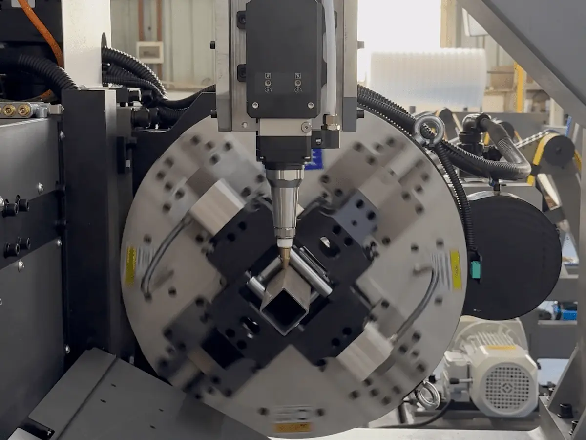
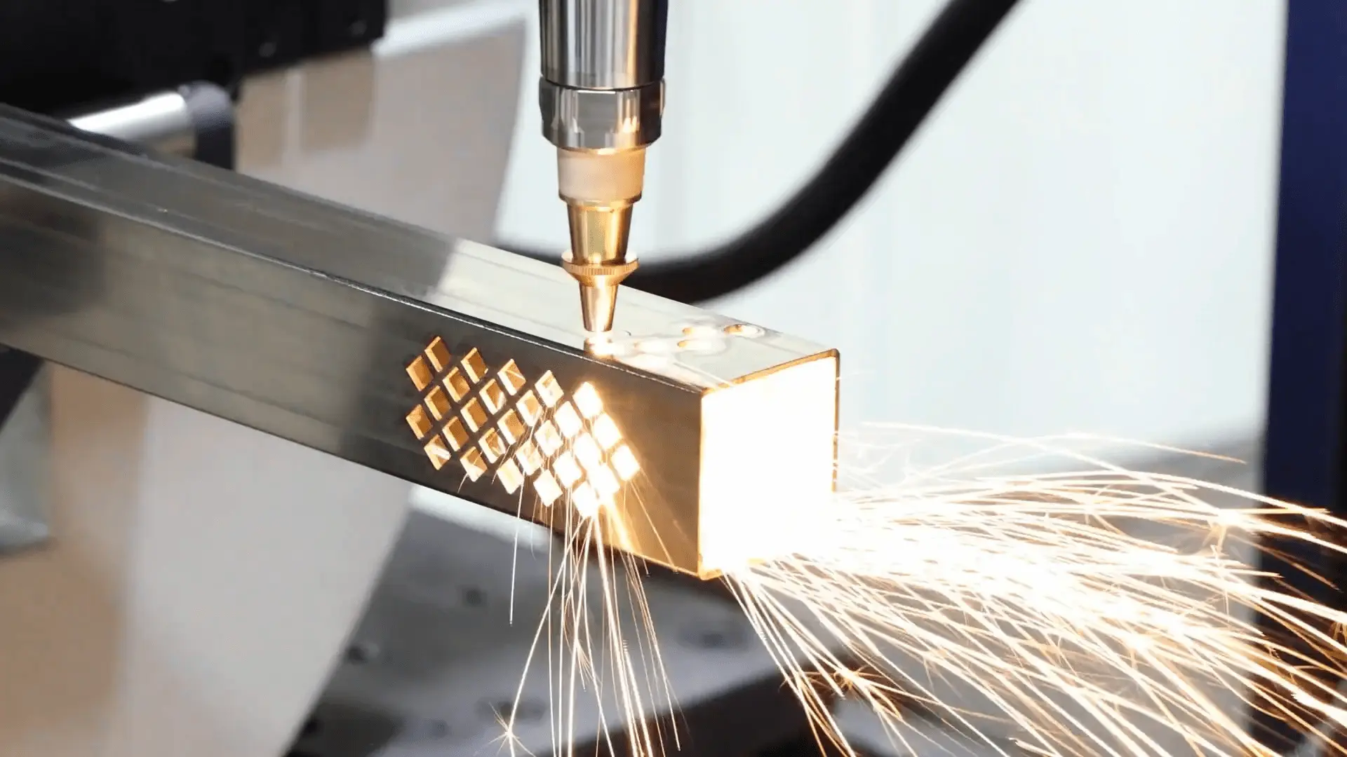
5. Fly Cutting in Laser Cutting Machines: A High‑Speed Piercing Method
In the context of laser cutting, fly cutting (also called flying cutting or scanning cutting) is a specialized strategy for piercing and cutting multiple circular or regular holes without lifting the laser head between each cut. By maintaining continuous motion and intelligently toggling the beam, this method delivers dramatic efficiency gains on parts with repeated hole patterns.
If you would like to learn more about fly cutting technology in laser cutting, please refer to this article: “What is Fly Cutting Technology in Laser Cutting Machines?”
6. Summary: Two Meanings, One Term
-
Fly Cutter in Milling
A face milling tool with one (or two) single‑point cutting bits mounted on an arbor. It produces ultra‑flat surfaces through slow, shallow passes and excels in applications like mold plate finishing, engine block surfacing, and spoilboard leveling. Its simplicity, low tooling cost, and customizable geometry make it a timeless choice for precision finishing—even though it’s not suited for heavy material removal or complex contours. -
Fly Cutting in Laser Systems
Also known as scanning or flying cutting, this method keeps the laser head in continuous motion, toggling the beam on/off to pierce multiple holes or shapes arranged in regular patterns. By leveraging path optimization, tangential transitions, and precise beam control, it dramatically reduces cycle time, minimizes wear, and improves energy efficiency—ideal for high‑volume perforations in automotive, electronics, and metal fabrication.
Understanding both definitions allows manufacturers and engineers to choose the right “fly cutting” approach for their specific needs—whether they require a single‑point milling solution for mirror finishes or a high‑speed laser strategy for repetitive hole patterns.