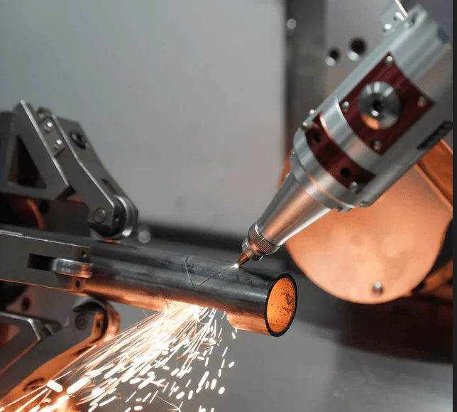
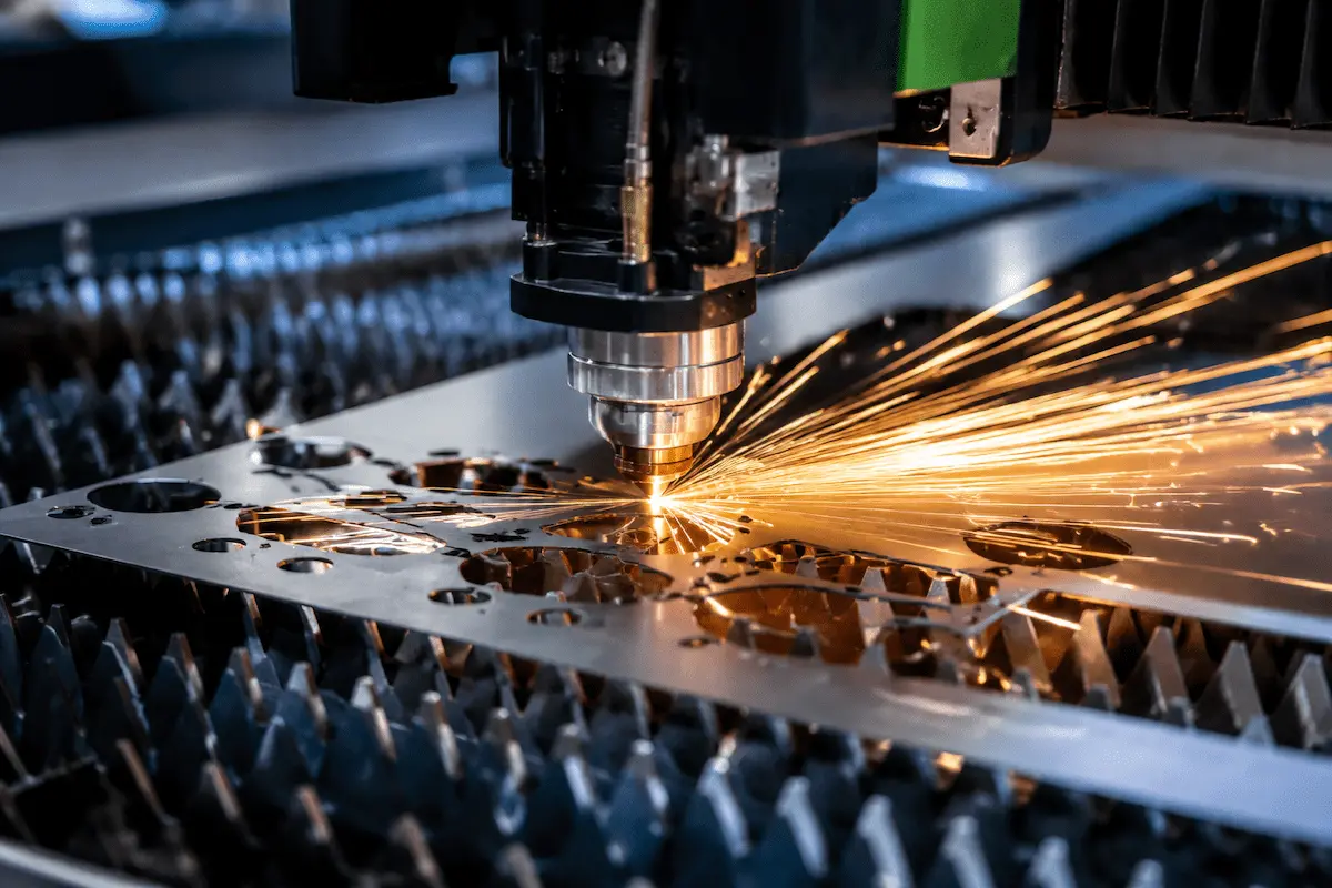
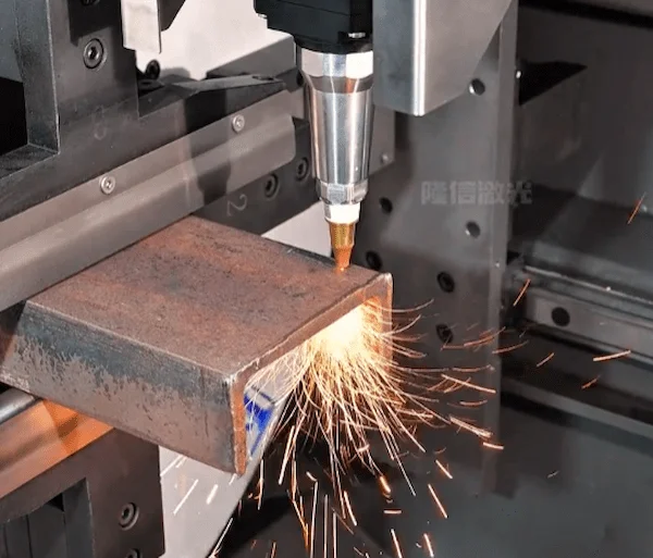
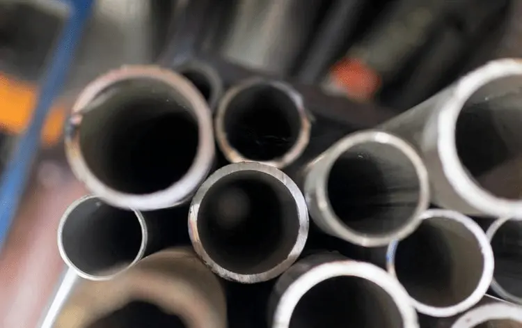
管材雷射切割機正以其高精度、速度、多功能性、減少廢料及自動化,深刻改變管材的傳統加工方式。選擇正確的 金屬管材雷射切割機 設備對於優化生產力、降低成本及提升產品品質至關重要。本文將為您提供選擇雷射管材切割機的參考指南。.
確認管徑與長度
最大管徑:
確保機器的夾頭/框架能夾持您最大尺寸的管材。夾頭直徑本身指的是其能夾緊的最大管材尺寸,因此選擇略高於管材最大直徑的夾頭最為理想。.
例如,Φ220 mm夾頭可夾持最大220 mm的管材,Φ350 mm夾頭可夾持最大350 mm的管材,依此類推。若加工管壁厚度最高12mm、最大管徑φ220mm、最長管材長度5.5m,且僅需切斷,無需穿孔、雕刻等工序,則根據此需求,我們可搭配夾頭直徑φ220mm、長度6m的設備。這些數據剛好能滿足客戶需求。.
最大管材長度:
檢查雷射管材切割機上料裝置的行程。常見型號可處理最長6–12 m的原料。若您需從較長原料切割多段短管,配備全自動送料功能的加長床身機型更為理想。.
管材長度也會影響雷射管材切割機的送料系統。.
送料系統的搭配
- 短管(<1公尺):適合手動送料或簡單的自動送料系統。.
- 中長度管材(1-6公尺):需配備標準自動上料與下料系統,以提高生產效率。.
- 長管(>6公尺):需配備強化型自動送料系統及支撐裝置,以防止管材在加工過程中彎曲或下垂。.
確認管材形狀
管材的截面形狀會影響夾持與切割穩定性。標準形狀——圓形、方形及矩形——幾乎所有雷射管材切割機都能輕鬆處理。.
先進機型能良好支援這些形狀;例如,某型號可切割最大250×150mm的矩形管。若您的工件包含特殊型材(如橢圓管、U型/C型槽鋼、「T」或「L」型材,或客製擠壓型材),則可能需要額外的夾持裝置。.
一般來說,型材越不規則,越多夾頭(或獨立夾爪)越有利。對於高度不規則的形狀,通常建議採用4夾爪(四夾頭)配置(其為客製型材提供額外夾緊)。對於略微非圓形的形狀(橢圓、多邊形、斜角管),3夾爪系統通常已足夠,但需注意對位精度。.
圓管/矩形管/方管:
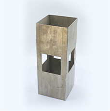
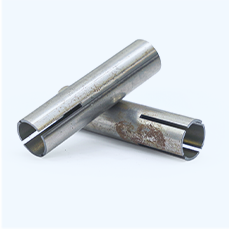
標準管材雷射機(配備2或3個夾頭)可輕鬆處理這些管材。只需確保夾頭夾爪或筒夾與管材形狀匹配即可。方形等多面形狀通常有專用的方形轉接器。.
不規則型材:
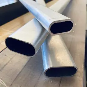
橢圓形或非對稱管材較難對中與切割。若您需大量切割此類型材,請選擇至少配備3個夾頭(以提供額外支撐)的機型,並詢問是否有第4夾頭選項。額外的夾頭能更牢固地夾持管材,提升異形件的切割精度。.
複雜開放式截面:
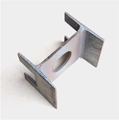
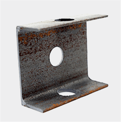
如工字樑、槽鋼或「H」型管等工件,應逐案評估。部分雷射管材切割機可配備特殊夾具或滾輪來夾持開放式截面;如有需要,請與供應商討論。.
確認管材加工需求
除直線切割外,請確認管材所需的任何額外加工。許多應用需要在管材上鑽孔、開槽、倒角或攻牙:
鑽孔/沖孔:
雷射可透過定點停留或使用高功率脈衝來鑽孔,但速度較慢。若您需要大量鑽孔或開槽,請確認機台是否提供鑽孔/穿孔附件。部分雷射管材切割機整合小型CNC鑽孔或沖孔裝置,用於孔洞與槽口加工,在大批量或長批次生產中可能比純雷射鑽孔快得多。.
坡口切割:
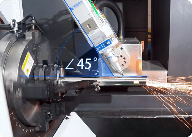
若設計需要斜角端面(焊接前準備),您應選擇配備坡口切割頭選項的機型(例如,, LX-T16坡口雷射切管機)。坡口切割頭可使雷射傾斜(通常最大45°)以產生斜角切割。這是許多機型的選配模組。若您省略坡口切割頭,機台將僅能進行垂直切割。.
攻牙/螺紋加工:
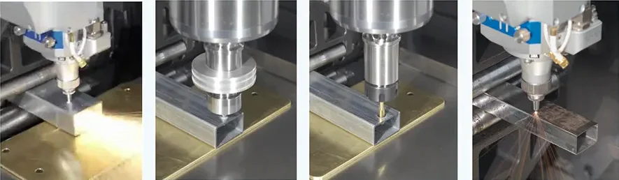
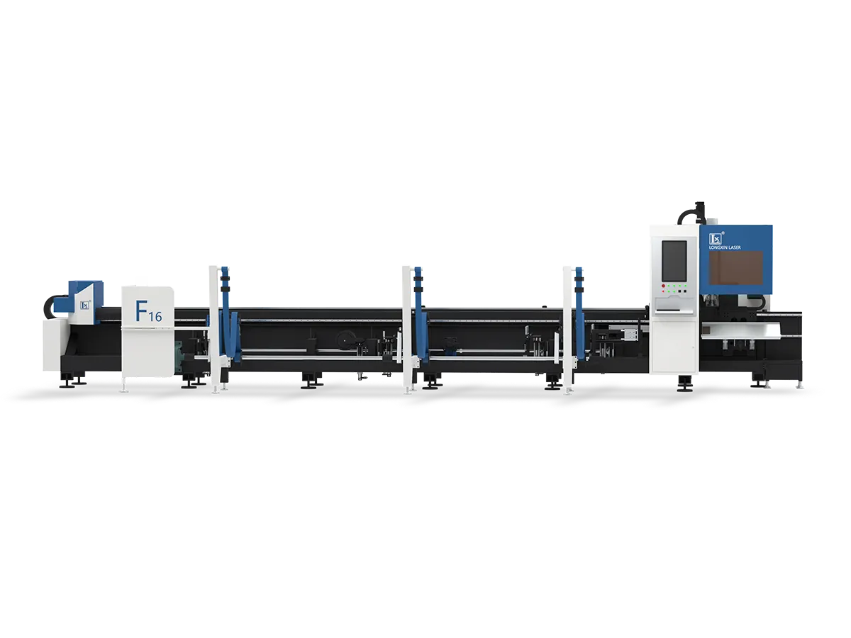
標準雷射無法直接切削螺紋。攻牙通常需使用機械絲攻或螺紋銑刀進行。部分先進雷射管材切割機(LX-F16)提供選配的自動攻牙或螺紋銑削工具,可在一次裝夾中完成。若您的工件需要螺紋端或螺紋孔,請詢問機台是否能整合攻牙單元,或攻牙是否必須在切割後另行處理。.
確認管材重量與穩定性
重型或長管材需格外謹慎。厚壁管或極長棒材可能因自身重量而下垂,進而影響切割品質。在評估機台時,請檢查:
支撐系統:
穩固的支撐系統至關重要。許多雷射管材切割機使用隨滑座移動的浮動尾端支撐。此「跟隨」支撐可在送料時保持管材高度恆定,防止下垂。配備浮動支撐時,上料與旋轉過程能保持穩定,並避免管材下垂。.
部分供應商將進階版本稱為「智慧型支撐」——其可自動調整以適應管材輪廓或撓曲。進行重型加工時,務必選擇支撐點靠近切割頭的機型。.
重量限制:
請確認機台可處理的最大管材重量。此數值通常以管材的「每公尺最大重量」表示。超過此限制可能使馬達過載或導致送料失誤。若您加工極厚鋼材(高密度)管材,請選擇專為該負載設計的機型。.
上料設備:
對於極重的管材,您可能需要內建式上料機或天車介面。部分機型配備整合式夾持台或自動升降裝置,用於重型管材。.
確認夾頭配置(2夾頭或更多?)
您應已根據管徑與切割長度決定夾頭尺寸,接著需考量雷射切割過程的穩定性、精度及尾料。一般而言,夾頭(夾爪)的數量決定了機台夾持管材的穩定性及尾料多寡。.
雙夾頭系統:
此類系統在頭部設有一個固定夾頭,並在尾端設有一個可移動的尾座夾頭。它們較為簡單且通常成本較低,適合一般圓管或方管。雙夾頭機台常見於中小型工件加工。.
一般雙夾頭雷射切管機通常會留下較長的尾料(最後一次切割與管端之間的部分),因為一旦切割位置進入夾頭可及範圍,剩餘的管段便成為廢料。此外,僅有兩個夾持點時,極重或極長的管材較易發生變形。.
然而,隨著技術持續演進,2025年已有雷射切管機(LX-K9-5) that use only two chucks to achieve 0 ends, comparable to the results of three chucks. The technical principle is that before cutting the last part of the tube, the laser cutting head lifts up, allowing the front chuck to move forward and clamp the tube out of the rear carat, achieving 0-tail material processing at the end.
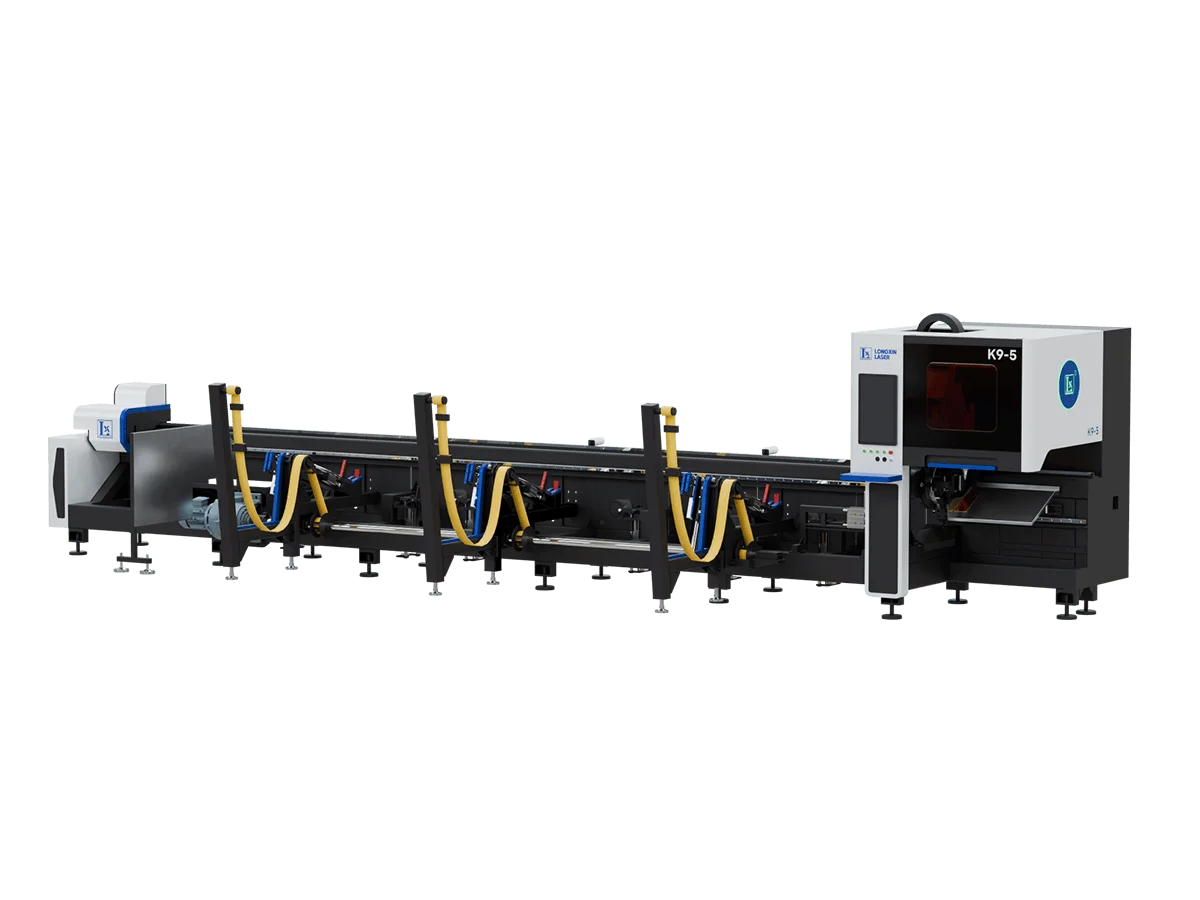
3-Chuck Systems:
Here, 2 chuck drive the tube and a third (usually fixed near the headstock) provides an extra clamp mid-length. This configuration locks the tube more firmly, which improves cutting accuracy on longer parts and reduces vibration. Importantly, a 3-chucks system can feed the tube fully, often achieving zero tail waste as the machine pushes the entire tube through.
Manufacturers note that 3-chuck laser tube cutters are versatile and cost-effective (cheaper than adding a whole extra head). The downside is slightly higher complexity and price than a 2-chuck machine, but with higher throughput and efficiency.
Choice Tip:
- If your tube work is primarily standard shape cutting and moderate lengths, a regular 2 chuck laser tube cutter will suffice.
- If you want to minimise tailing, a 2 chuck machine with front chuck avoidance, or a regular 3 chuck machine is more worth the investment.
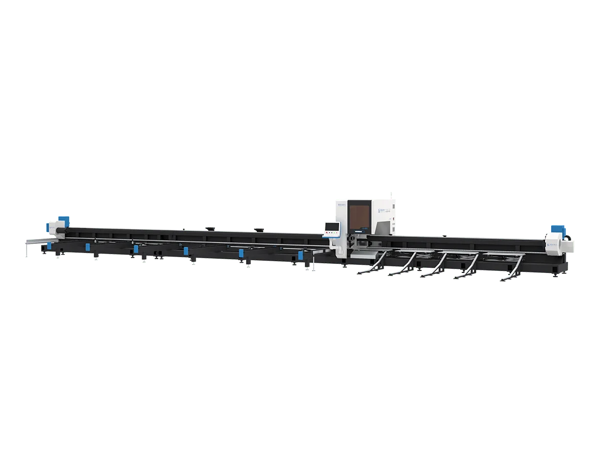
- For complex profiles, high-precision, heavy-duty, and extra-long tubes, a customised laser tube cutting machine, possibly with 4 or more chucks, is required.
- More chucks are not always better. An increase in the number of chucks means a redesign of the mechanical structure, which can significantly increase the cost of the machinery and usually requires customisation, which is time-consuming.
6. Automation (Loading/Unloading) needs
For high-volume or heavy work, consider machines with automatic loading and unloading systems. These use conveyors or robotic arms to feed tubes into the laser and remove cut parts, drastically increasing throughput and reducing manual labor. Auto-loading is optional but valuable if you cut many similar tubes; it also improves safety (no manual lifting).
If budget is tight and volumes are low, you can load tubes by hand, but ensure you have means (like a clamp table) to manually secure them.
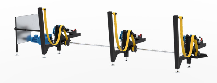
Support Systems (Follow/Intelligent)
Beyond the basic tailstock, modern machines offer enhanced tube support:
- Floating (Follow) Support: This support rolls on rails under the tube and moves along with the cutting head. It keeps supporting the end of the tube continuously as it feeds, preventing the rear from sagging or vibrating. This is essential for long or very flexible tubes.
- Fixed Tailstock: Older or simpler machines use a fixed tailstock that doesn’t move. This is fine for short lengths, but as soon as you cut away the tube end, the remaining part can droop once it’s only supported at one end.
- Intelligent Support: Some advanced cutters have sensors that detect tube curvature or deflection and automatically adjust the support height. This “smart” system maintains a constant focus-to-tube distance even on warped tubes. If you deal with bent or inconsistent material, ask about this feature.
7. Choose a Laser Tube Cutting Machine Based on Processing Accuracy
(1) High-Precision Applications (Medical Devices, Electronic Components)
Key Requirements: Cutting accuracy ≤±0.05mm, smooth cut surfaces, minimal heat-affected zones.
Equipment Configuration Requirements
| Component | Specifications |
| 雷射源 | Fiber laser, 1500-3000W power, beam quality M²<1.1 |
| Beam Spot Diameter | ≤0.02mm (ultra-fine spot for thin materials) |
| Repeat Positioning Accuracy | X/Y-axis: ±0.03mm, Rotary axis: ±0.05° |
| Machine Rigidity | Cast iron bed + FEA-optimized structure, vibration resistance ≥50Hz |
| Cutting Head | Auto-focus cutting head with ceramic nozzle (1.0-1.5mm aperture) |
| Control System | Pulse cutting capability, process database, real-time monitoring |
| Auxiliary Systems | High-purity nitrogen (≥99.999%), water chiller (±0.5°C stability) |
Process Optimization
- Parameters: Speed 1-2m/min (1mm stainless steel), pulse frequency >2000Hz
- Gas Selection: Nitrogen for stainless steel (12-15bar), oxygen for carbon steel (8-10bar)
- Typical Applications: Surgical instrument brackets (0.5mm titanium alloy), micro-connectors (1mm copper alloy)
(2) Medium-Thick Material Batch Production (Construction, Heavy Machinery)
Key Requirements: Cutting thickness 8-20mm, high efficiency, continuous operation stability.
Equipment Configuration Requirements
| Component | Specifications |
| 雷射源 | Fiber laser, 4000-12000W power, power fluctuation <±2% |
| Beam Spot Diameter | 0.05-0.1mm (balances speed and precision) |
| Repeat Positioning Accuracy | X/Y-axis: ±0.05mm, Rotary axis: ±0.1° |
| Machine Rigidity | Welded steel structure with cross-bracing, load capacity ≥2000kg |
| Cutting Head | Anti-reflection coating, quick-change nozzle design |
| Control System | Batch file processing, automatic nesting |
| Auxiliary Systems | Dual-pump water cooling (±1°C stability), dust removal ≥6000m³/h |
Process Optimization
- Parameters: Speed 0.5-1.5m/min (12mm carbon steel), oxygen assist (1.5-2MPa)
- Efficiency: Automatic loader integration, nozzle change time <10s
- Typical Applications: Bridge steel structures (16mm Q355), hydraulic cylinder tubes (10mm 45# steel)
(3) Special Material Processing (Titanium Alloy, Galvanized Steel)
Key Requirements: Handling reflective/oxidizable/high-melting-point materials.
Equipment Configuration Requirements
| Component | Specifications |
| 雷射源 | Disk laser or anti-reflection fiber laser, ≥6000W power |
| Beam Spot Diameter | 0.03-0.06mm (high energy density) |
| Repeat Positioning Accuracy | X/Y-axis: ±0.04mm, Rotary axis: ±0.08° |
| Machine Rigidity | Fully enclosed splash-proof structure, corrosion-resistant coating |
| Cutting Head | Gold-coated mirrors + dual gas channels (independent inner/outer gas control) |
| Control System | Material database (pre-loaded parameters for titanium/galvanized steel) |
| Auxiliary Systems | Dual gas supply (nitrogen + compressed air), zinc fume filtration |
Process Optimization
- Titanium Cutting: Argon shielding (prevents oxidation), focus position offset -0.2~-0.5mm
- Galvanized Steel: Pre-purge mode removes zinc layer, 20% lower gas pressure
- Typical Applications: Aerospace titanium tubing (5mm TC4), HVAC ducts (3mm SGCC)
(4) General Metal Tube Processing (Furniture, Windows/Doors)
Key Requirements: Cutting thickness 1-6mm, cost-effectiveness, easy maintenance.
Equipment Configuration Requirements
| Component | Specifications |
| 雷射源 | Fiber laser, 1000-2000W power, cost-optimized |
| Beam Spot Diameter | 0.05-0.1mm |
| Repeat Positioning Accuracy | X/Y-axis: ±0.1mm, Rotary axis: ±0.2° |
| Machine Rigidity | Lightweight welded structure, load capacity ≥500kg |
| Cutting Head | Manual focus adjustment, copper nozzle (200hr lifespan) |
| Control System | User-friendly interface, CAD direct import |
| Auxiliary Systems | Single-pump water chiller (±2°C), standard air compressor (0.8MPa) |
Process Optimization
- Parameters: Speed 2-4m/min (2mm carbon steel), oxygen assist (0.6-0.8MPa)
- Cost Control: Compressed air instead of nitrogen (acceptable for thin stainless steel)
- Typical Applications: Stainless steel railings (3mm 304), aluminum window frames (2mm 6061)
(5) Summary: Scenario-Based Selection Logic
| Scenario | Priority Order | Budget Allocation |
| High-Precision | Precision > Stability > Power | 60%+ on equipment |
| Medium-Thick Batch | Power > Efficiency > Maintenance | 50%+ on laser source |
| Special Materials | Specialization > Power > Safety | 40%+ on gas systems |
| General Processing | Cost > Usability > Basic Accuracy | 80%+ on base machine |
Note: Always request sample cutting tests to verify machine-material compatibility.
8. Optional Process Modules For Laser Tube Cutting Machine
Many tube lasers can add specialized modules. Consider these if your work demands:
(1) Beveling Head:
This tilts the laser head (commonly ±45° or more) to cut angled ends for weld joints. Specify the required maximum bevel angle. Not all machines include this by default.
(2) Drilling/Tapping Unit:
Some systems have an optional drill or tapping tool to make holes or threads. If you need threaded holes in tube walls, either a tap-up kit or a combined laser/tap machine is needed.
(3) Roll-Bending or Forming:
Occasionally, combined machines can also bend or form tubes. If so, these will be advertised as specialized multi-function units.
(4) Material Handling Attachments:
Options like bundle loaders (for multiple tubes at once), cross-cutting attachments, or stackers may be offered for higher automation levels.
結論
List all your tube specs (sizes, shapes, materials, wall thicknesses, required operations) and go down this checklist. Compare suppliers’ machine data to ensure each critical attribute is covered. Choosing the right tube laser cutter involves balancing your tube characteristics against the machine’s features (diameter/length capacity, chuck type, supports, power, and optional modules) to find the best fit for your production needs.