เครื่องตัดเลเซอร์ท่อกำลังเปลี่ยนแปลงวิธีการแปรรูปท่อแบบดั้งเดิมอย่างลึกซึ้ง ด้วยความแม่นยำสูง ความเร็ว ความหลากหลาย การลดของเสีย และระบบอัตโนมัติ การเลือกเครื่องที่เหมาะสม เครื่องตัดเลเซอร์หลอด เป็นสิ่งสำคัญอย่างยิ่งในการเพิ่มประสิทธิภาพการผลิต ลดต้นทุน และปรับปรุงคุณภาพผลิตภัณฑ์ บทความนี้จะให้ข้อมูลอ้างอิงสำหรับการเลือกเครื่องตัดเลเซอร์ท่อที่เหมาะสม.
ยืนยันเส้นผ่านศูนย์กลางและความยาวของท่อ
เส้นผ่านศูนย์กลางท่อสูงสุด:
ตรวจสอบให้แน่ใจว่าหัวจับ/โครงของเครื่องสามารถจับท่อขนาดใหญ่ที่สุดของคุณได้ เส้นผ่านศูนย์กลางของหัวจับหมายถึงขนาดท่อสูงสุดที่สามารถหนีบได้ ดังนั้นการเลือกหัวจับที่ใหญ่กว่าเส้นผ่านศูนย์กลางสูงสุดของท่อเล็กน้อยจึงเหมาะสมที่สุด.
ตัวอย่างเช่น หัวจับ Φ220 มม. สามารถจับท่อได้สูงสุด 220 มม. หัวจับ Φ350 มม. จับได้สูงสุด 350 มม. เป็นต้น การแปรรูปท่อที่มีความหนาผนังสูงสุด 12 มม. เส้นผ่านศูนย์กลางท่อสูงสุด φ220 มม. ความยาวท่อสูงสุด 5.5 ม. ต้องการเพียงการตัดออก โดยไม่ต้องเจาะรู แกะสลัก และกระบวนการอื่นๆ ตามข้อกำหนดนี้ เราสามารถจับคู่กับอุปกรณ์ที่มีหัวจับเส้นผ่านศูนย์กลาง φ220 มม. ความยาว 6 ม. ข้อมูลเหล่านี้เพียงพอต่อความต้องการของลูกค้า.
ความยาวท่อสูงสุด:
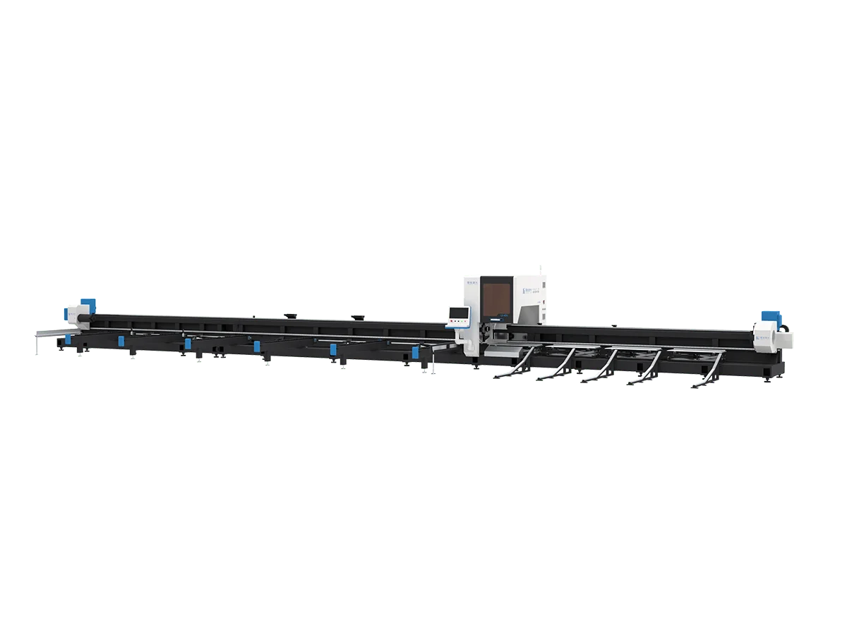
ตรวจสอบระยะเคลื่อนที่ของตัวป้อนเครื่องตัดเลเซอร์ท่อ รุ่นทั่วไปรองรับวัสดุยาวสูงสุด 6–12 ม. เครื่องที่มีฐานยาวและระบบป้อนเต็มรูปแบบเหมาะอย่างยิ่งหากคุณตัดชิ้นส่วนสั้นจำนวนมากจากวัสดุยาว.
ความยาวของท่อยังส่งผลต่อระบบป้อนของเครื่องตัดเลเซอร์ท่ออีกด้วย.
การปรับตัวของระบบป้อน
- ท่อสั้น (<1 เมตร): เหมาะสำหรับการป้อนด้วยมือหรือระบบป้อนอัตโนมัติแบบง่าย.
- ท่อความยาวปานกลาง (1-6 เมตร): จำเป็นต้องติดตั้งระบบป้อนและขนถ่ายอัตโนมัติมาตรฐานเพื่อเพิ่มผลผลิต.
- ท่อความยาวมาก (>6 เมตร): ต้องใช้ระบบป้อนอัตโนมัติที่เพิ่มประสิทธิภาพและตัวรองรับเพื่อป้องกันท่องอหรือหย่อนระหว่างการแปรรูป.
ยืนยันรูปทรงของท่อ
รูปทรงหน้าตัดของท่อมีผลต่อการจับยึดและความเสถียรในการตัด รูปทรงมาตรฐาน – กลม สี่เหลี่ยมจัตุรัส และสี่เหลี่ยมผืนผ้า – สามารถจัดการได้ง่ายโดยเครื่องตัดเลเซอร์ท่อเกือบทุกรุ่น.
เครื่องขั้นสูงรองรับรูปทรงเหล่านี้ได้ดี ตัวอย่างเช่น รุ่นหนึ่งตัดท่อสี่เหลี่ยมผืนผ้าได้สูงสุด 250×150 มม. หากชิ้นส่วนของคุณมีโปรไฟล์พิเศษ (เช่น ท่อวงรี รางรูปตัวยู/ซี รูปทรง “ที” หรือ “แอล” หรือการอัดขึ้นรูปพิเศษ) คุณอาจต้องใช้อุปกรณ์จับยึดเพิ่มเติม.
โดยทั่วไป ยิ่งโปรไฟล์ไม่สม่ำเสมอมากเท่าใด การมีหัวจับมากขึ้น (หรือขากรรไกรอิสระ) ก็ยิ่งมีประโยชน์ การตั้งค่าแบบ 4 ขากรรไกร (สี่หัวจับ) มักแนะนำสำหรับรูปทรงที่ไม่สม่ำเสมออย่างมาก (ให้การหนีบพิเศษสำหรับโปรไฟล์พิเศษ) สำหรับรูปทรงที่ไม่กลมเล็กน้อย (วงรี รูปหลายเหลี่ยม ท่อมุม) ระบบ 3 ขากรรไกรมักเพียงพอ แต่ต้องใส่ใจการจัดตำแหน่ง.
ท่อกลม/สี่เหลี่ยมผืนผ้า/สี่เหลี่ยมจัตุรัส:
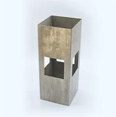
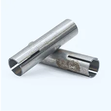
เครื่องตัดเลเซอร์ท่อมาตรฐาน (ที่มี 2 หรือ 3 หัวจับ) จัดการสิ่งเหล่านี้ได้โดยไม่มีปัญหา เพียงตรวจสอบให้แน่ใจว่าขากรรไกรหรือปลอกรองจับของหัวจับตรงกับรูปทรงท่อ รูปทรงหลายเหลี่ยมเช่นสี่เหลี่ยมจัตุรัสมักมีอะแดปเตอร์สี่เหลี่ยมเฉพาะ.
โปรไฟล์ที่ไม่สม่ำเสมอ:
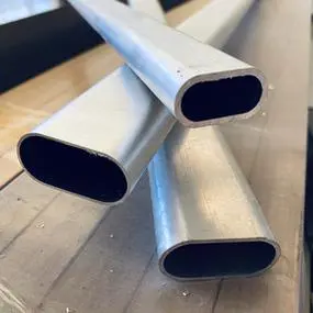
ท่อวงรีหรือไม่สมมาตรยากต่อการตั้งศูนย์และตัด หากคุณต้องการตัดโปรไฟล์ดังกล่าวจำนวนมาก ให้เลือกเครื่องที่มีอย่างน้อย 3 หัวจับ (เพื่อการรองรับพิเศษ) และสอบถามว่ามีตัวเลือกหัวจับที่ 4 หรือไม่ หัวจับพิเศษยึดท่อได้แน่นขึ้น ปรับปรุงความแม่นยำบนรูปทรงที่แปลก.
หน้าตัดเปิดที่ซับซ้อน:
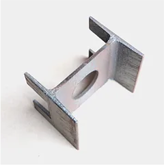
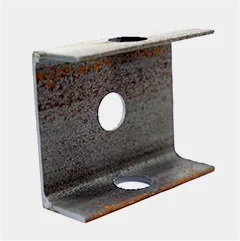
ชิ้นงานเช่น ไอบีม รางน้ำ หรือท่อ “เอช” ควรตรวจสอบเป็นกรณีๆ ไป เครื่องตัดเลเซอร์ท่อบางรุ่นสามารถติดตั้งแคลมป์พิเศษหรือลูกกลิ้งเพื่อยึดหน้าตัดเปิดได้ ปรึกษากับซัพพลายเออร์หากจำเป็น.
ยืนยันข้อกำหนดการแปรรูปท่อ
นอกเหนือจากการตัดตรงแล้ว ให้พิจารณาถึงการตัดเฉือนเพิ่มเติมใดๆ ที่ท่อของคุณต้องการ งานหลายประเภทต้องการรู ร่องบาก มุมเอียง หรือเกลียวบนท่อ:
การเจาะรู/การปั๊มรู:
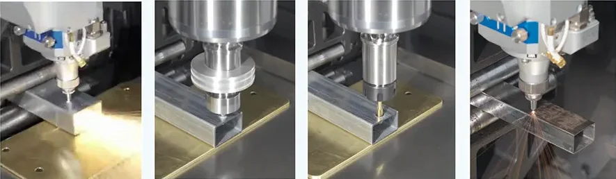
เลเซอร์สามารถสร้างรูได้โดยการหยุดลำแสงที่จุดใดจุดหนึ่งหรือใช้พัลส์กำลังสูง แต่วิธีนี้ทำได้ช้า หากคุณต้องการรูเจาะหรือร่องยาวจำนวนมาก ให้ตรวจสอบว่าเครื่องมีอุปกรณ์เสริมสำหรับเจาะ/ปั๊มหรือไม่ เครื่องตัดท่อเลเซอร์บางรุ่นรวมหัวเจาะหรือปั๊ม CNC ขนาดเล็กสำหรับทำรูและร่องบาก ซึ่งอาจเร็วกว่าการเจาะด้วยเลเซอร์เพียงอย่างเดียวมากสำหรับงานปริมาณมากหรือท่อยาว.
การตัดมุมเอียง:
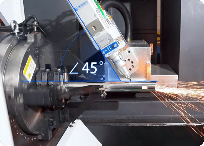
หากการออกแบบต้องการปลายท่อที่ทำมุม (การเตรียมรอยเชื่อม) คุณควรเลือกเครื่องที่มีตัวเลือกหัวตัดมุมเอียง (ตัวอย่างเช่น, LX-T16 Bevelling Laser Pipe Cutting Machine) หัวตัดมุมเอียงจะเอียงหัวเลเซอร์ (โดยทั่วไปสูงสุด 45°) เพื่อสร้างการตัดที่ทำมุม นี่เป็นโมดูลเสริมในเครื่องหลายรุ่น หากคุณไม่เลือกหัวตัดมุมเอียง เครื่องจะทำการตัดในแนวตั้งฉากเท่านั้น.
การทำเกลียว/การต๊าปเกลียว:
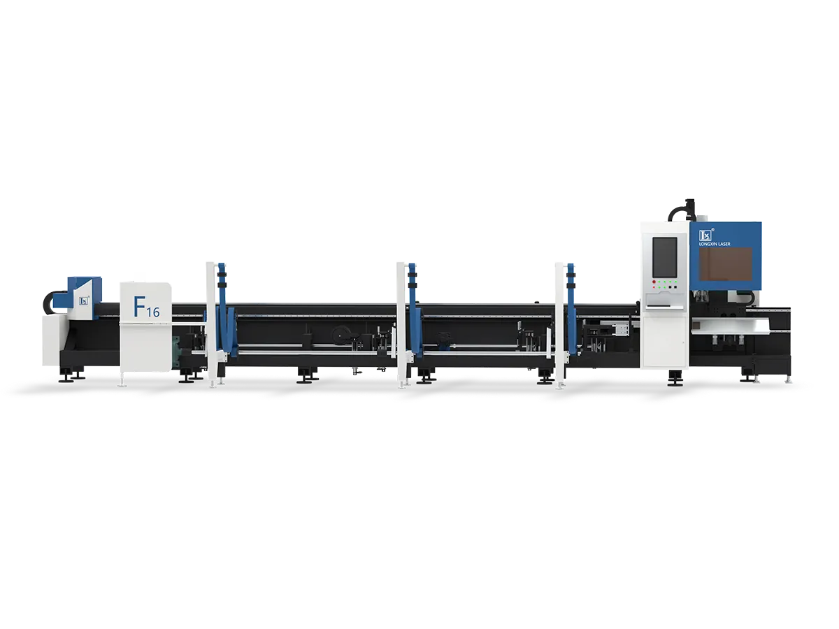
เลเซอร์มาตรฐานไม่สามารถตัดเกลียวสกรูได้โดยตรง การต๊าปเกลียวมักทำด้วยต๊าปเกลียวเชิงกลหรือหัวกัดเกลียว เครื่องตัดท่อเลเซอร์ขั้นสูงบางรุ่น (LX-F16) มีเครื่องมือต๊าปเกลียวหรือกัดเกลียวอัตโนมัติเสริมที่สามารถใช้ได้ในการตั้งค่าเดียว หากชิ้นส่วนของคุณต้องการปลายหรือรูที่มีเกลียว ให้สอบถามว่าเครื่องสามารถรวมหน่วยต๊าปเกลียวได้หรือไม่ หรือต้องทำการต๊าปเกลียวแยกต่างหากหลังการตัด.
ยืนยันน้ำหนักและความเสถียรของท่อ
ท่อที่มีน้ำหนักมากหรือยาวต้องใช้ความระมัดระวังเป็นพิเศษ ท่อที่มีผนังหนาหรือแท่งยาวมากอาจหย่อนตัวลงด้วยน้ำหนักของตัวเอง ซึ่งส่งผลต่อคุณภาพการตัด เมื่อคุณกำลังประเมินเครื่องจักร โปรดตรวจสอบ:
ระบบรองรับ:
ระบบรองรับที่แข็งแรงเป็นสิ่งสำคัญ เครื่องตัดท่อเลเซอร์หลายรุ่นใช้ตัวรองรับท้ายแบบลอยตัวที่เคลื่อนที่ไปกับแคร่ ตัวรองรับแบบ “ตาม” นี้ช่วยรักษาความสูงของท่อให้คงที่ขณะป้อนเข้า ป้องกันการหย่อนตัว ด้วยตัวรองรับแบบลอยตัว กระบวนการโหลดและหมุนจะเสถียรและหลีกเลี่ยงการหย่อนตัวของท่อ.
ผู้จำหน่ายบางรายเรียกรุ่นขั้นสูงว่า “ตัวรองรับอัจฉริยะ” – พวกมันปรับให้เข้ากับรูปร่างหรือการโค้งงอของท่อโดยอัตโนมัติ เลือกเครื่องที่มีตัวรองรับวางใกล้กับหัวตัดเสมอสำหรับงานหนัก.
ขีดจำกัดน้ำหนัก:
ตรวจสอบน้ำหนักท่อสูงสุดที่เครื่องสามารถรองรับได้ โดยปกติจะระบุเป็น “น้ำหนักสูงสุดต่อเมตร” สำหรับท่อ การเกินค่านี้อาจทำให้มอเตอร์ทำงานหนักเกินไปหรือเกิดการป้อนผิดพลาด หากคุณทำงานกับท่อเหล็กหนามาก (ความหนาแน่นสูง) ให้เลือกเครื่องที่ออกแบบมาสำหรับภาระนั้น.
อุปกรณ์โหลด:
สำหรับท่อที่มีน้ำหนักมาก คุณอาจต้องใช้ตัวโหลดในตัวหรืออินเทอร์เฟซเครน เครื่องบางรุ่นมีโต๊ะจับยึดในตัวหรือลิฟต์อัตโนมัติสำหรับท่อหนัก.
ยืนยันการกำหนดค่าหัวจับ (2 หัวจับหรือมากกว่า?)
คุณควรตัดสินใจเลือกขนาดของหัวจับตามเส้นผ่านศูนย์กลางของท่อและความยาวของการตัดแล้ว จากนั้นคุณต้องคิดถึงความเสถียรของกระบวนการตัดเลเซอร์ ความแม่นยำ และเศษปลายท่อ โดยทั่วไป จำนวนหัวจับ (ขากรรไกร) จะกำหนดความเสถียรของการจับยึดท่อของเครื่องรวมถึงเศษปลายท่อ.
ระบบ 2 หัวจับ:
ระบบเหล่านี้มีหัวจับคงที่หนึ่งตัวที่หัวเครื่องและหัวจับท้ายแท่นแบบเคลื่อนที่ได้หนึ่งตัว เรียบง่ายกว่าและโดยทั่วไปถูกกว่า เหมาะสำหรับท่อกลมหรือสี่เหลี่ยมทั่วไป เครื่องสองหัวจับเป็นเรื่องปกติสำหรับงานขนาดเล็กถึงกลาง.
เครื่องตัดท่อเลเซอร์สองหัวจับทั่วไปมักจะเหลือเศษปลายท่อยาว (ส่วนของท่อระหว่างการตัดครั้งสุดท้ายกับปลายท่อ) เพราะเมื่อการตัดอยู่ในระยะที่หัวจับเอื้อมถึง ส่วนที่เหลือจะกลายเป็นเศษ นอกจากนี้ ด้วยจุดจับยึดเพียงสองจุด ท่อที่มีน้ำหนักมากหรือยาวมากมีแนวโน้มที่จะเสียรูปมากขึ้น.
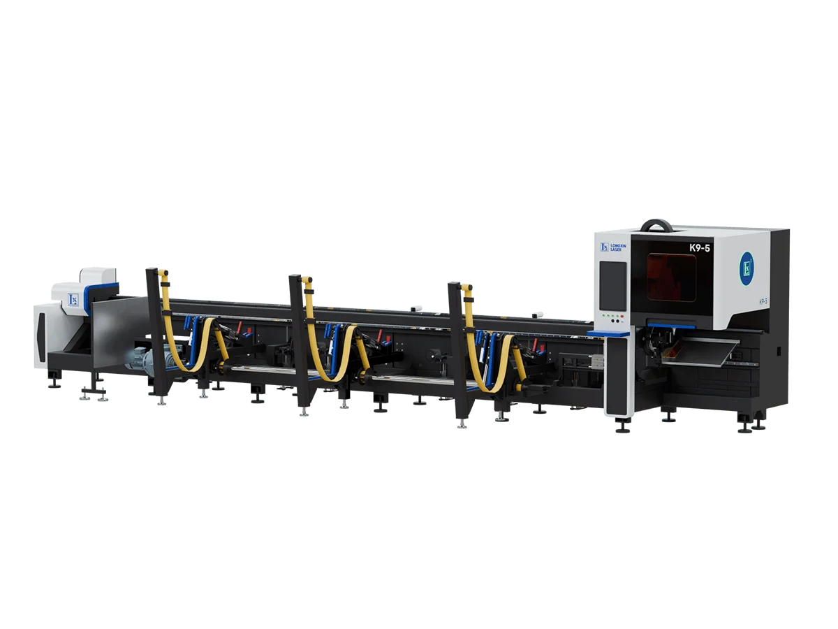
อย่างไรก็ตาม ในขณะที่เทคโนโลยียังคงพัฒนาอย่างต่อเนื่อง ในปี 2025 ก็มีเครื่องตัดท่อด้วยเลเซอร์ (LX-K9-5) ที่ใช้เพียงสองหัวจับเพื่อให้ได้ปลายตัด 0 ชิ้น เทียบเท่ากับผลลัพธ์ของสามหัวจับ หลักการทางเทคนิคคือ ก่อนตัดชิ้นส่วนสุดท้ายของท่อ หัวตัดเลเซอร์จะยกขึ้น ทำให้หัวจับด้านหน้าสามารถเคลื่อนไปข้างหน้าและจับท่อออกจากหัวจับด้านหลังได้ ทำให้ได้การแปรรูปวัสดุปลายตัด 0 ที่ปลายท่อ.
ระบบสามหัวจับ:
ที่นี่ หัวจับ 2 ตัวขับเคลื่อนท่อ และหัวจับที่สาม (มักจะยึดอยู่ใกล้หัวเครื่อง) ให้การจับยึดเพิ่มเติมที่กึ่งกลางความยาว การกำหนดค่านี้ยึดท่อได้แน่นหนาขึ้น ซึ่งช่วยปรับปรุงความแม่นยำในการตัดชิ้นส่วนที่ยาวขึ้นและลดการสั่นสะเทือน ที่สำคัญ ระบบสามหัวจับสามารถป้อนท่อได้เต็มที่ มักจะได้ของเสียปลายตัดเป็นศูนย์เมื่อเครื่องดันท่อทั้งหมดผ่านเข้าไป.
ผู้ผลิตระบุว่าเครื่องตัดท่อเลเซอร์แบบสามหัวจับมีความหลากหลายและคุ้มค่า (ถูกกว่าการเพิ่มหัวตัดพิเศษทั้งชุด) ข้อเสียคือมีความซับซ้อนและราคาสูงกว่าเครื่องสองหัวจับเล็กน้อย แต่มีอัตราการผลิตและประสิทธิภาพสูงกว่า.
เคล็ดลับการเลือก:
- หากงานท่อของคุณส่วนใหญ่เป็นการตัดรูปทรงมาตรฐานและความยาวปานกลาง เครื่องตัดท่อเลเซอร์สองหัวจับทั่วไปก็เพียงพอ.
- หากคุณต้องการลดเศษปลายท่อให้เหลือน้อยที่สุด เครื่องสองหัวจับที่มีระบบหลีกเลี่ยงหัวจับด้านหน้า หรือเครื่องสามหัวจับทั่วไปคุ้มค่าต่อการลงทุนมากกว่า.
- สำหรับโปรไฟล์ที่ซับซ้อน ความแม่นยำสูง งานหนัก และท่อที่ยาวเป็นพิเศษ จำเป็นต้องใช้เครื่องตัดท่อเลเซอร์ที่ปรับแต่งเฉพาะ ซึ่งอาจมีหัวจับ 4 ตัวขึ้นไป.
- การมีหัวจับมากขึ้นไม่ได้ดีเสมอไป การเพิ่มจำนวนหัวจับหมายถึงการออกแบบโครงสร้างเครื่องจักรใหม่ ซึ่งสามารถเพิ่มต้นทุนของเครื่องจักรได้อย่างมาก และมักต้องมีการปรับแต่งเฉพาะ ซึ่งใช้เวลานาน.
ความต้องการระบบอัตโนมัติ (การโหลด/การขนถ่าย)
สำหรับงานปริมาณมากหรืองานหนัก พิจารณาเครื่องจักรที่มีระบบโหลดและขนถ่ายอัตโนมัติ ระบบเหล่านี้ใช้สายพานลำเลียงหรือแขนหุ่นยนต์เพื่อป้อนท่อเข้าเครื่องเลเซอร์และนำชิ้นส่วนที่ตัดออก เพิ่มอัตราการผลิตอย่างมากและลดแรงงานคน การโหลดอัตโนมัติเป็นทางเลือก แต่มีคุณค่าหากคุณตัดท่อที่คล้ายกันจำนวนมาก อีกทั้งยังปรับปรุงความปลอดภัย (ไม่ต้องยกด้วยมือ).
หากงบประมาณจำกัดและปริมาณน้อย คุณสามารถโหลดท่อด้วยมือได้ แต่ต้องแน่ใจว่ามีอุปกรณ์ (เช่น โต๊ะจับยึด) เพื่อยึดท่อด้วยตนเอง.

ระบบรองรับ (แบบติดตาม/อัจฉริยะ)
นอกเหนือจากท้ายเครื่องพื้นฐาน เครื่องจักรสมัยใหม่มีการรองรับท่อที่ดียิ่งขึ้น:
- ตัวรองรับแบบลอย (ติดตาม): ตัวรองรับนี้เคลื่อนที่บนรางใต้ท่อและเคลื่อนที่ไปพร้อมกับหัวตัด มันรองรับปลายท่ออย่างต่อเนื่องในขณะที่ป้อน ป้องกันไม่ให้ส่วนท้ายหย่อนหรือสั่นสะเทือน ซึ่งจำเป็นสำหรับท่อยาวหรือท่อที่ยืดหยุ่นมาก.
- ท้ายเครื่องแบบยึดติด: เครื่องจักรเก่าหรือเครื่องที่ง่ายกว่าใช้ท้ายเครื่องแบบยึดติดที่ไม่เคลื่อนที่ เหมาะสำหรับความยาวสั้น แต่ทันทีที่คุณตัดปลายท่อออก ส่วนที่เหลืออาจหย่อนลงเมื่อรองรับเพียงปลายเดียว.
- ตัวรองรับอัจฉริยะ: เครื่องตัดขั้นสูงบางรุ่นมีเซนเซอร์ที่ตรวจจับความโค้งหรือการโก่งตัวของท่อ และปรับความสูงของตัวรองรับโดยอัตโนมัติ ระบบ “อัจฉริยะ” นี้รักษาระยะโฟกัสถึงท่อให้คงที่แม้บนท่อที่บิดเบี้ยว หากคุณทำงานกับวัสดุที่งอหรือไม่สม่ำเสมอ ให้สอบถามเกี่ยวกับคุณสมบัตินี้.
เลือกเครื่องตัดท่อเลเซอร์ตามความแม่นยำในการประมวลผล
(1) การใช้งานที่ต้องการความแม่นยำสูง (อุปกรณ์การแพทย์ ชิ้นส่วนอิเล็กทรอนิกส์)
ข้อกำหนดหลัก: ความแม่นยำในการตัด ≤±0.05 มม. พื้นผิวตัดเรียบ โซนรับความร้อนน้อยที่สุด.
ข้อกำหนดการกำหนดค่าอุปกรณ์
| ส่วนประกอบ | ข้อกำหนด |
| แหล่งกำเนิดเลเซอร์ | เลเซอร์ไฟเบอร์ กำลัง 1500-3000W คุณภาพลำแสง M²<1.1 |
| เส้นผ่านศูนย์กลางจุดลำแสง | ≤0.02 มม. (จุดละเอียดพิเศษสำหรับวัสดุบาง) |
| ความแม่นยำการวางตำแหน่งซ้ำ | แกน X/Y: ±0.03 มม. แกนหมุน: ±0.05° |
| ความแข็งแกร่งของเครื่องจักร | ฐานเหล็กหล่อ + โครงสร้างที่ปรับด้วย FEA ความต้านทานการสั่นสะเทือน ≥50Hz |
| หัวตัด | หัวตัดโฟกัสอัตโนมัติพร้อมหัวฉีดเซรามิก (รู 1.0-1.5 มม.) |
| ระบบควบคุม | ความสามารถในการตัดแบบพัลส์ ฐานข้อมูลกระบวนการ การตรวจสอบแบบเรียลไทม์ |
| ระบบเสริม | ไนโตรเจนความบริสุทธิ์สูง (≥99.999%) เครื่องทำน้ำเย็น (ความเสถียร ±0.5°C) |
การปรับกระบวนการให้เหมาะสม
- พารามิเตอร์: ความเร็ว 1-2 ม./นาที (สแตนเลส 1 มม.) ความถี่พัลส์ >2000Hz
- การเลือกแก๊ส: ไนโตรเจนสำหรับสแตนเลส (12-15 บาร์) ออกซิเจนสำหรับเหล็กกล้าคาร์บอน (8-10 บาร์)
- การใช้งานทั่วไป: ขายึดเครื่องมือผ่าตัด (โลหะผสมไทเทเนียม 0.5 มม.) ขั้วต่อขนาดเล็ก (โลหะผสมทองแดง 1 มม.)
(2) การผลิตชุดวัสดุความหนาปานกลาง (การก่อสร้าง เครื่องจักรกลหนัก)
ข้อกำหนดหลัก: ความหนาการตัด 8-20 มม. ประสิทธิภาพสูง ความเสถียรในการทำงานต่อเนื่อง.
ข้อกำหนดการกำหนดค่าอุปกรณ์
| ส่วนประกอบ | ข้อกำหนด |
| แหล่งกำเนิดเลเซอร์ | เลเซอร์ไฟเบอร์ กำลัง 4000-12000W ความผันผวนของกำลัง <±2% |
| เส้นผ่านศูนย์กลางจุดลำแสง | 05-0.1 มม. (สมดุลระหว่างความเร็วและความแม่นยำ) |
| ความแม่นยำการวางตำแหน่งซ้ำ | แกน X/Y: ±0.05 มม. แกนหมุน: ±0.1° |
| ความแข็งแกร่งของเครื่องจักร | โครงสร้างเหล็กเชื่อมพร้อมค้ำยัน ความสามารถในการรับน้ำหนัก ≥2000 กก. |
| หัวตัด | การเคลือบป้องกันการสะท้อน การออกแบบหัวฉีดเปลี่ยนเร็ว |
| ระบบควบคุม | การประมวลผลไฟล์เป็นชุด การจัดเรียงชิ้นส่วนอัตโนมัติ |
| ระบบเสริม | ระบบระบายความร้อนด้วยน้ำแบบปั๊มคู่ (ความเสถียร ±1°C) ระบบกำจัดฝุ่น ≥6000 ลบ.ม./ชม. |
การปรับกระบวนการให้เหมาะสม
- พารามิเตอร์: ความเร็ว 0.5-1.5 ม./นาที (เหล็กกล้าคาร์บอน 12 มม.) ใช้ออกซิเจนช่วย (1.5-2MPa)
- ประสิทธิภาพ: การรวมระบบโหลดอัตโนมัติ เวลาเปลี่ยนหัวฉีด <10 วินาที
- การใช้งานทั่วไป: โครงสร้างเหล็กสะพาน (Q355 หนา 16 มม.), ท่อกระบอกไฮดรอลิก (เหล็ก 45# หนา 10 มม.)
(3) การแปรรูปวัสดุพิเศษ (ไทเทเนียมอัลลอยด์, เหล็กชุบสังกะสี)
ข้อกำหนดหลัก: การจัดการวัสดุที่สะท้อนแสง/ออกซิไดซ์ได้/มีจุดหลอมเหลวสูง.
ข้อกำหนดการกำหนดค่าอุปกรณ์
| ส่วนประกอบ | ข้อกำหนด |
| แหล่งกำเนิดเลเซอร์ | เลเซอร์ดิสก์หรือไฟเบอร์เลเซอร์ป้องกันการสะท้อน กำลัง ≥6000W |
| เส้นผ่านศูนย์กลางจุดลำแสง | 03-0.06 มม. (ความหนาแน่นพลังงานสูง) |
| ความแม่นยำการวางตำแหน่งซ้ำ | แกน X/Y: ±0.04 มม., แกนหมุน: ±0.08° |
| ความแข็งแกร่งของเครื่องจักร | โครงสร้างกันกระเด็นแบบปิดสนิท เคลือบสารป้องกันการกัดกร่อน |
| หัวตัด | กระจกเคลือบทอง + ช่องแก๊สคู่ (ควบคุมแก๊สภายใน/ภายนอกแยกอิสระ) |
| ระบบควบคุม | ฐานข้อมูลวัสดุ (พารามิเตอร์ที่โหลดไว้ล่วงหน้าสำหรับไทเทเนียม/เหล็กชุบสังกะสี) |
| ระบบเสริม | ระบบจ่ายแก๊สคู่ (ไนโตรเจน + ลมอัด), ระบบกรองควันสังกะสี |
การปรับกระบวนการให้เหมาะสม
- การตัดไทเทเนียม: ใช้แก๊สอาร์กอนป้องกัน (ป้องกันการออกซิเดชัน), ชดเชยตำแหน่งโฟกัส -0.2~-0.5 มม.
- เหล็กชุบสังกะสี: โหมดไล่แก๊สล่วงหน้าเพื่อขจัดชั้นสังกะสี, ความดันแก๊สล่าง 20%
- การใช้งานทั่วไป: ท่อไทเทเนียมการบินและอวกาศ (TC4 หนา 5 มม.), ท่อ HVAC (SGCC หนา 3 มม.)
(4) การแปรรูปท่อโลหะทั่วไป (เฟอร์นิเจอร์, หน้าต่าง/ประตู)
ข้อกำหนดหลัก: ความหนาการตัด 1-6 มม., ความคุ้มค่า, บำรุงรักษาง่าย.
ข้อกำหนดการกำหนดค่าอุปกรณ์
| ส่วนประกอบ | ข้อกำหนด |
| แหล่งกำเนิดเลเซอร์ | ไฟเบอร์เลเซอร์ กำลัง 1000-2000W, ปรับต้นทุนให้เหมาะสม |
| เส้นผ่านศูนย์กลางจุดลำแสง | 05-0.1 มม. |
| ความแม่นยำการวางตำแหน่งซ้ำ | แกน X/Y: ±0.1 มม., แกนหมุน: ±0.2° |
| ความแข็งแกร่งของเครื่องจักร | โครงสร้างเชื่อมน้ำหนักเบา ความสามารถในการรับน้ำหนัก ≥500 กก. |
| หัวตัด | ปรับโฟกัสด้วยมือ, หัวฉีดทองแดง (อายุการใช้งาน 200 ชั่วโมง) |
| ระบบควบคุม | อินเทอร์เฟซใช้งานง่าย, นำเข้า CAD โดยตรง |
| ระบบเสริม | เครื่องทำความเย็นน้ำปั๊มเดี่ยว (±2°C), เครื่องอัดอากาศมาตรฐาน (0.8MPa) |
การปรับกระบวนการให้เหมาะสม
- พารามิเตอร์: ความเร็ว 2-4 ม./นาที (เหล็กกล้าคาร์บอน 2 มม.), ใช้ออกซิเจนช่วย (0.6-0.8MPa)
- การควบคุมต้นทุน: ใช้ลมอัดแทนไนโตรเจน (ใช้ได้กับสแตนเลสบาง)
- การใช้งานทั่วไป: ราวสแตนเลส (304 หนา 3 มม.), กรอบหน้าต่างอะลูมิเนียม (6061 หนา 2 มม.)
(5) สรุป: ตรรกะการเลือกตามสถานการณ์
| สถานการณ์ | ลำดับความสำคัญ | การจัดสรรงบประมาณ |
| ความแม่นยำสูง | ความแม่นยำ > ความเสถียร > กำลัง | 60%+ กับอุปกรณ์ |
| ชิ้นงานหนาปานกลางแบบจำนวนมาก | กำลัง > ประสิทธิภาพ > การบำรุงรักษา | 50%+ กับแหล่งกำเนิดเลเซอร์ |
| วัสดุพิเศษ | ความเชี่ยวชาญ > กำลัง > ความปลอดภัย | 40%+ กับระบบแก๊ส |
| การแปรรูปทั่วไป | ต้นทุน > ความใช้งานง่าย > ความแม่นยำพื้นฐาน | 80%+ กับตัวเครื่องพื้นฐาน |
หมายเหตุ: ควรขอทดลองตัดชิ้นงานเพื่อตรวจสอบความเข้ากันได้ของเครื่องจักรและวัสดุเสมอ.
โมดูลกระบวนการเสริมสำหรับเครื่องตัดท่อด้วยเลเซอร์
เครื่องตัดท่อด้วยเลเซอร์หลายรุ่นสามารถเพิ่มโมดูลเฉพาะทางได้ พิจารณาโมดูลเหล่านี้หากงานของคุณต้องการ:
(1) หัวตัดมุมเอียง:
หัวนี้เอียงหัวเลเซอร์ (โดยทั่วไป ±45° หรือมากกว่า) เพื่อตัดปลายมุมสำหรับรอยเชื่อม ระบุมุมเอียงสูงสุดที่ต้องการ ไม่ใช่ทุกเครื่องที่จะมีฟังก์ชันนี้เป็นค่าเริ่มต้น.
(2) ชุดเจาะ/ทำเกลียว:
บางระบบมีเครื่องเจาะหรือทำเกลียวเสริมสำหรับทำรูหรือเกลียว หากคุณต้องการเกลียวในผนังท่อ จำเป็นต้องใช้ชุดทำเกลียวหรือเครื่องจักรผสมเลเซอร์/ทำเกลียว.
(3) การดัดม้วนหรือการขึ้นรูป:
Occasionally, combined machines can also bend or form tubes. If so, these will be advertised as specialized multi-function units.
(4) Material Handling Attachments:
Options like bundle loaders (for multiple tubes at once), cross-cutting attachments, or stackers may be offered for higher automation levels.
สรุป
List all your tube specs (sizes, shapes, materials, wall thicknesses, required operations) and go down this checklist. Compare suppliers’ machine data to ensure each critical attribute is covered. Choosing the right tube laser cutter involves balancing your tube characteristics against the machine’s features (diameter/length capacity, chuck type, supports, power, and optional modules) to find the best fit for your production needs.