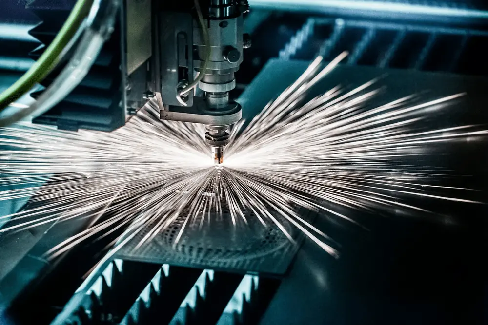
1. บทนำเกี่ยวกับฟังก์ชันการตัดแบบฟลายคัทของเครื่องตัดเลเซอร์
การตัดแบบฟลายคัท หรือที่เรียกว่าการตัดแบบบินหรือการตัดแบบสแกน หมายถึงวิธีการตัดที่หัวเลเซอร์เคลื่อนที่จากชิ้นงานหนึ่งไปยังอีกชิ้นงานหนึ่งโดยไม่ยกขึ้นในระหว่างกระบวนการตัดชิ้นงานวงกลมหรือชิ้นงานที่มีรูในเป็นวงกลม วิธีการนี้ช่วยเพิ่มประสิทธิภาพการตัดได้อย่างมาก.
เมื่อรูบนวัสดุท่อมีรูปทรงปกติ (เช่น วงกลม สี่เหลี่ยมผืนผ้า) และจัดเรียงในรูปแบบที่แน่นอน การตัดแบบฟลายคัทสามารถเชื่อมต่อส่วนต่างๆ ในทิศทางเดียวกันเพื่อการตัดต่อเนื่อง ซึ่งช่วยเพิ่มความเร็วในการตัดและประหยัดเวลาในการประมวลผลได้อย่างมาก.
เทคโนโลยีนี้ถูกนำไปใช้อย่างแพร่หลายในงานแปรรูปโลหะ การผลิตยานยนต์ อุปกรณ์อิเล็กทรอนิกส์ และสาขาอื่นๆ อีกมากมาย เนื่องจากมีประสิทธิภาพสูงและความแม่นยำ.
2. หลักการของเทคโนโลยีการตัดแบบฟลายคัทด้วยเลเซอร์
เทคโนโลยีการตัดแบบฟลายคัทอาศัยอุปกรณ์ตัดเลเซอร์ที่มีความแม่นยำสูง ซึ่งสามารถควบคุมการเคลื่อนที่ของลำแสงเลเซอร์ได้อย่างรวดเร็วและแม่นยำ เทคนิคขั้นสูงนี้แสดงถึงการเปลี่ยนแปลงพื้นฐานจากวิธีการตัดแบบลำดับดั้งเดิมไปสู่การปรับเส้นทางให้เหมาะสมอย่างชาญฉลาด.
(1) กลไกหลักของการตัดแบบฟลายคัท
กลยุทธ์การปรับเส้นทางให้เหมาะสม
หัวใจหลักของการตัดแบบฟลายคัทคือการใช้อัลกอริทึมการปรับเส้นทางให้เหมาะสมที่ซับซ้อน ซึ่งช่วยให้หัวเลเซอร์เคลื่อนที่ในรูปแบบกริดที่มีประสิทธิภาพ แทนที่จะตัดชิ้นงานหนึ่งให้เสร็จก่อนเคลื่อนที่ไปยังชิ้นงานถัดไป ระบบจะดำเนินการตัดเส้นแนวนอนและแนวตั้ง พร้อมกับเปิดและปิดเลเซอร์อย่างมีกลยุทธ์ที่ขอบเฉพาะ วิธีการนี้ช่วยให้สามารถประมวลผลการตัดหลายรายการพร้อมกัน ลดเวลารอบการทำงานโดยรวมลงอย่างมาก.
การเปลี่ยนทิศทางอย่างชาญฉลาด
เมื่อหัวเลเซอร์เปลี่ยนทิศทาง จะใช้การเปลี่ยนผ่านรัศมีสัมผัสแทนการเลี้ยวแบบมุมแหลม เทคนิคนี้มีวัตถุประสงค์สองประการ:
- ลดเวลาในการตัดโดยรักษาความเร็วตัดที่เหมาะสมตลอดการเปลี่ยนผ่าน
- ลดการสึกหรอทางกลของส่วนประกอบอุปกรณ์ ยืดอายุการใช้งานของเครื่องจักร
ความแม่นยำในการควบคุมเลเซอร์
ระบบควบคุมจังหวะการเปิดใช้งานเลเซอร์อย่างแม่นยำ โดยเปิดและปิดลำแสงในช่วงเวลาที่แน่นอน เพื่อให้แน่ใจว่าการตัดสะอาดพร้อมลดเวลาการทำงานของเลเซอร์ที่ไม่จำเป็น การเปิดใช้งานแบบเลือกนี้ช่วยทั้งประสิทธิภาพการใช้พลังงานและคุณภาพการตัดที่ดีขึ้น.
(2) ข้อได้เปรียบเหนือวิธีการแบบดั้งเดิม
ข้อจำกัดของวิธีการแบบดั้งเดิม: การตัดเลเซอร์แบบดั้งเดิมใช้วิธีการเส้นทางเดียว ซึ่งหัวเลเซอร์ต้องตัดแต่ละชิ้นงานให้เสร็จก่อนเคลื่อนที่ไปยังงานถัดไป วิธีการแบบลำดับนี้ แม้จะเชื่อถือได้ แต่ใช้เวลานานโดยธรรมชาติสำหรับโครงการที่มีรูปแบบซ้ำๆ หลายรูปแบบ.
3. ประเภทต่างๆ ของฟังก์ชันการตัดแบบฟลายคัทด้วยเลเซอร์
(1) การตัดแบบฟลายคัทแนวโค้ง
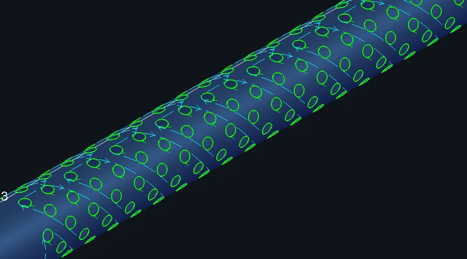
สำหรับรูวงกลม ที่จัดเรียงอย่างเป็นระเบียบ, ไม่ว่าจะบนท่อกลมหรือท่อสี่เหลี่ยม, ควรใช้การตัดแบบฟลายคัทแนวโค้ง ควรใช้.
ระยะทางสูงสุดสำหรับการเชื่อมต่อแบบบินระหว่างวงกลม: เมื่อระยะห่างจุดเริ่มต้นระหว่างรูวงกลมน้อยกว่าพารามิเตอร์ที่ตั้งไว้ สามารถสร้างเส้นตัดแบบฟลายคัทได้ แนะนำให้ตั้งค่าพารามิเตอร์นี้ให้ใหญ่กว่าระยะห่างระหว่างรูวงกลมเล็กน้อย.
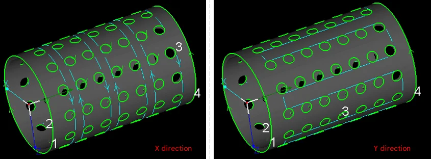
ทิศทางการจัดเรียง: ทิศทางของเส้นทางการตัดสำหรับการตัดแบบฟลายคัทกำหนดลำดับการตัดของรู.
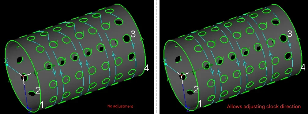
การปรับทิศทางตามเข็มนาฬิกาของส่วนโค้งอัตโนมัติ: เมื่อรูวงกลมมีตำแหน่งเริ่มต้นและทิศทางการตัดที่แตกต่างกัน เส้นฟลายคัทที่สร้างขึ้นอาจดูยุ่งเหยิงและเส้นทางการเคลื่อนที่ฟลายคัทไม่ราบรื่น เว้นแต่จะมีข้อกำหนดพิเศษ แนะนำให้เลือกการปรับอัตโนมัติ หลังจากเลือกแล้ว ซอฟต์แวร์จะปรับทิศทางการตัดของรูวงกลมแต่ละรูตามเส้นทางการเคลื่อนที่ฟลายคัทโดยอัตโนมัติ.
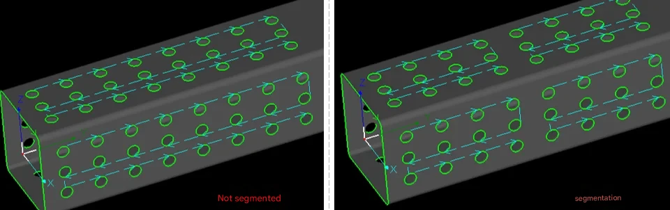
การฟลายคัทแบบแบ่งส่วน: สำหรับชิ้นงานยาว แนะนำให้ใช้การฟลายคัทแบบแบ่งส่วนเพื่อหลีกเลี่ยงการเคลื่อนที่ไปข้างหน้าและถอยหลังบ่อยครั้งของวัสดุท่อในระยะทางไกลตามทิศทางแกน Y.
สำหรับ การจัดเรียงแบบสลับ การตั้งค่าฟลายคัทกราฟิก:
(2) การฟลายคัทเชิงเส้น
สำหรับรูสี่เหลี่ยมผืนผ้าหรือรูเพชรที่จัดเรียงอย่างเป็นระเบียบโดยไม่มีมุมมน ไม่ว่าจะบนท่อกลมหรือท่อสี่เหลี่ยมผืนผ้า, การฟลายคัทเชิงเส้น ควรใช้.
ค่าเบี่ยงเบนระยะทางที่อนุญาต: เมื่อเชื่อมต่อส่วนบนเส้นตรงเดียวกันด้วยเส้นฟลายคัท ส่วนที่มีค่าเบี่ยงเบนระยะทางจากเส้นตรงน้อยกว่าค่าที่ตั้งไว้นี้จะถูกวางแผนให้อยู่ในเส้นทางการฟลายคัทนี้ด้วย ค่าเริ่มต้นคือ 20 มม.

ระยะทางสูงสุดสำหรับการเชื่อมต่อราบรื่น: เมื่อเปลี่ยนจากฟลายคัทแถวหนึ่งไปยังอีกแถวหนึ่ง ระยะห่างการเลี้ยวที่น้อยกว่าค่าที่ตั้งไว้นี้สามารถใช้การเชื่อมต่อราบรื่นได้ (ไม่แนะนำให้แก้ไขพารามิเตอร์นี้)
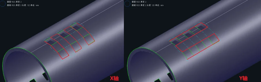
การจัดเรียง:
สำหรับฟลายคัท ค่าเริ่มต้นคือการตัดในทิศทาง X ก่อน จากนั้นจึงตัดในทิศทาง Y หลังจากเสร็จสิ้นทิศทาง X.
ในระหว่างกระบวนการจับยึดและเคลื่อนที่วัสดุท่อ วัสดุท่อที่ยังไม่ได้ตัดอาจยกตัวขึ้นในแคลมป์จับ หรือเศษที่ยังไม่หลุดออกอาจตกลงไปภายในแคลมป์จับระหว่างการจับยึด ทำให้แคลมป์เสียหายและส่งผลต่อความปลอดภัยของอุปกรณ์และคุณภาพการตัด ในกรณีนี้ สามารถสลับทิศทางการจัดเรียงของเส้นทางการเคลื่อนที่ได้อย่างอิสระ.
การฟลายคัทแบบแบ่งส่วน: สำหรับชิ้นงานยาว แนะนำให้ใช้การฟลายคัทแบบแบ่งส่วนเพื่อหลีกเลี่ยงการเคลื่อนที่ไปข้างหน้าและถอยหลังบ่อยครั้งของวัสดุท่อในระยะทางไกลตามทิศทางแกน Y.
(3) การฟลายคัทแบบต่อเนื่อง
การฟลายคัทแบบต่อเนื่องสามารถใช้กับรูทุกรูปทรง ยกเว้นข้อความ โดยทั่วไปใช้สำหรับตัดรูวงรีแบบอาร์เรย์ รูสี่เหลี่ยมผืนผ้ามน เป็นต้น.
รัศมีสูงสุดของเส้นฟลายคัทแนวโค้ง: รัศมีสูงสุดที่ใช้สำหรับการเปลี่ยนทิศทางของเส้นฟลายคัท แนะนำให้ใช้ค่าเริ่มต้นที่ 3 มม.
ความยาวเส้นฟลายสูงสุด: The maximum flying line length supported between two adjacent graphics.
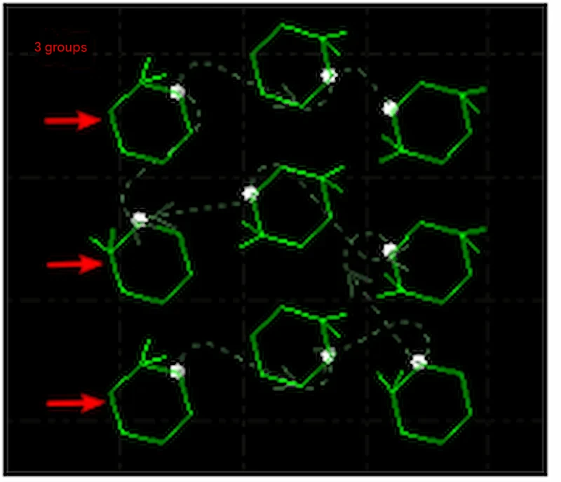
Serpentine sorting: Within the layout area, the cutting path presents a snake-like shape, as shown in the figure below:
Number of groups: The number of grid groups automatically divided for serpentine sorting.
4. What are the Advantages of Laser Fly Cutting?
(1) Significantly Save Time and Improve Work Efficiency
In traditional cutting mode, the cutting head needs to move from one location to another each time, with each movement consuming time. In fly cutting mode, the laser head flies directly to the target position and only starts working when actual cutting is needed. This means the entire cutting process no longer requires frequent stops and positioning, making cutting much faster than traditional methods, especially suitable for some long strip workpieces or high-volume processing requirements.
(2) Significantly Reduce Batch Production Costs
For single large parts, traditional cutting may be more efficient; but when involving more than 50 repeated graphics, fly cutting can save more than 60% of working hours. Longxin Laser uses intelligent nesting AI algorithms to achieve 92% steel utilization rate, significantly reducing batch production costs.
Fly cutting function is not suitable for all cutting tasks. To maximize the benefits of fly cutting function, detailed analysis of the workpiece material, thickness, and processing requirements is needed. For thicker metal materials, fly cutting mode may lead to unstable cutting quality, so it is necessary to choose whether to enable fly cutting function based on different situations. For thin plate materials or thin tubes, the effect of fly cutting is more obvious. It not only reduces wear caused by mechanical movement but also completes a large number of cutting tasks in a short time.
5. How to Use Laser Fly Cutting Function?
(1) Equipment and Material Preparation
Equipment Setup
- Verify that your laser cutting machine is equipped with fly cutting functionality
- Configure machine parameters based on material specifications:
- Adjust laser power according to material thickness
- Set appropriate cutting speed for the material type
- Calibrate the cutting head position
Material Setup
- Securely clamp the workpiece onto the cutting table
- Ensure proper material alignment and positioning
- Verify that the material surface is clean and free of debris
(2) Software Configuration and Programming
Step 1: Create or Import Graphics
- Open your cutting software (e.g., CypCut)
- Draw new graphics or import existing CAD files
- Focus on repetitive patterns such as circles, rectangles, or custom shapes
Step 2: Generate Pattern Arrays
- Select the base graphics that will be repeated
- Use the array function to create multiple copies:
- Set the number of rows and columns needed
- Define spacing between graphics (minimum 1mm to prevent collision)
- Preview the layout to ensure proper distribution
Step 3: Activate Fly Cutting Mode
- Locate the “Fly Cutting” option in the software interface (typically in the upper right corner)
- Select the appropriate fly cutting mode based on your graphics:
- ควรใช้การตัดแบบฟลายคัทแนวโค้ง: For circular holes and curved patterns
- การฟลายคัทเชิงเส้น: For rectangular or square openings
- Racetrack Fly Cutting: For oval or elongated shapes
- One-Stroke Fly Cutting: For complex geometries requiring continuous paths
Step 4: Optimize Cutting Parameters
- Cutting Sequence: Define the order of operations (e.g., left-to-right, top-to-bottom)
- Micro-tab Settings: Configure small connection points (0.1-0.3mm) at start/end positions to prevent part movement during cutting
- Maximum Jump Distance: Set the maximum distance (1-5mm) the laser head can travel between cuts without interrupting the fly cutting sequence
- การควบคุมความแม่นยำ: Adjust recognition deviation to 0.01mm accuracy to minimize path errors
(3) Execute Cutting Operation
Pre-Cutting Checklist
- Review the programmed cutting path and sequence
- Verify all safety systems are operational
- Ensure proper ventilation and fume extraction
During Cutting
- Monitor the cutting process continuously
- Watch for any irregularities in cut quality or machine behavior
- Be prepared to pause or stop the operation if issues arise
(4) Post-Cutting Quality Control
Immediate Inspection
- Examine cut edges for consistency and quality
- Check dimensional accuracy of finished parts
- Verify that all intended cuts were completed
Cleanup and Preparation
- Remove finished parts from the cutting table
- Clear away any cutting debris or slag
- Clean the worktable surface for the next operation
- Store completed parts according to quality standards
6. What are the Application Scenarios for Laser Fly Cutting?
Sheet Metal Dense Hole Processing
- Heat sinks/Filters: Efficiently cut large numbers of regularly arranged circular holes, square holes, or irregular holes, such as server chassis heat dissipation plates and air filter metal meshes. Fly cutting speed is more than 3 times faster than traditional methods.
- Architectural Decorative Panels: Hollow carving and railing grids on stainless steel/carbon steel thin plates (≤3mm). Complex patterns can be mass-produced through linear or arc fly cutting.
Pipe and Structural Component Processing
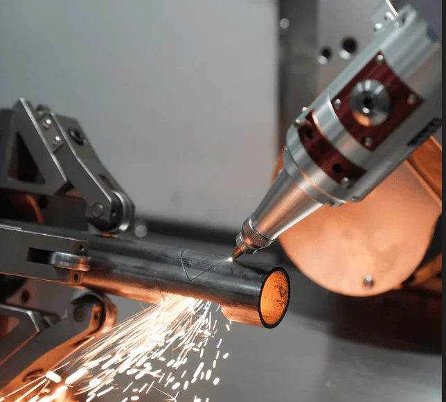
- Automotive Exhaust Pipes/Agricultural Machine Brackets: High-speed hole opening or cutting connection parts on round pipes and square pipes. Bond Laser T-series five-axis pipe cutting machines support fully automatic fly cutting for φ20-600mm pipes.
- Elevator Panels/Control Cabinets: Button holes and wire groove opening groups on thin steel plates, using one-stroke fly cutting mode to reduce empty movement paths.
Advertising Signs and Craft Gifts
- Metal Nameplates/Logos: Fine text hollowing on stainless steel or brass thin plates, such as corporate logos and artistic letters.
- Cultural and Creative Products: Laser hollow patterns on greeting cards and bookmarks (such as flowers, geometric patterns), three-dimensional assembly models of acrylic materials.
Consumer Electronics and Home Appliances
- Electrical Enclosure Heat Dissipation Holes: Group circular hole fly cutting on air conditioning panels and power box covers, requiring hole position accuracy of ±0.1mm.
- 3C Components: Mobile phone middle plate positioning holes, headphone metal mesh covers. Han’s Laser ultrafast laser technology achieves micron-level cutting.
7. Longxin Laser Fly Cutting Solutions
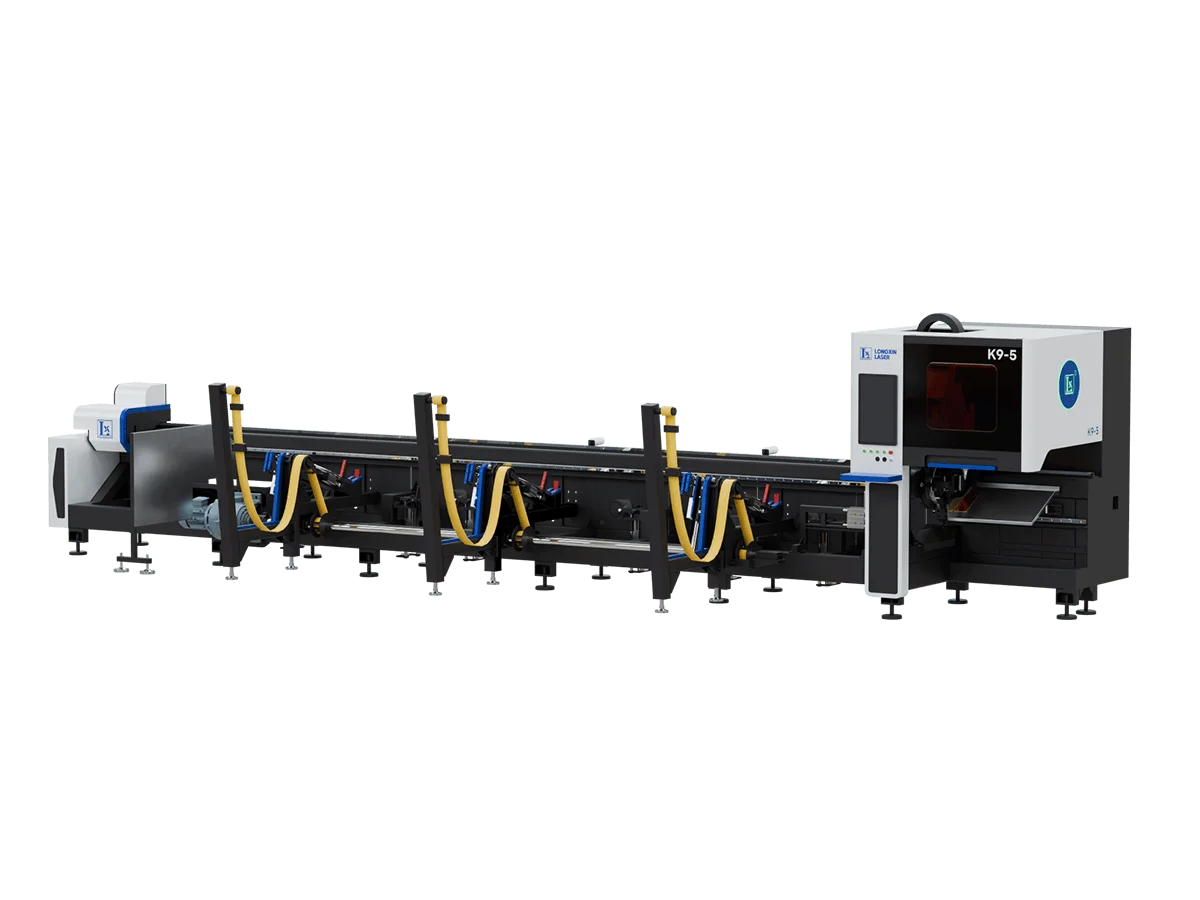
Longxin Laser offers advanced laser tube cutting machines equipped with cutting-edge fly cutting technology. Our machines feature high-performance capabilities with maximum acceleration up to 2.0G, ensuring rapid and precise processing for demanding industrial applications.