1. Introduction to Laser Cutting Machine Fly Cutting Function
Fly cutting, also known as flying cutting or scanning cutting, refers to a cutting method where the laser head moves from one part to the next without lifting during the process of cutting circular or parts with circular inner holes. This approach significantly improves cutting efficiency.
When the holes on the pipe material are regular shapes (such as circles, rectangles) and arranged in a certain regular pattern, fly cutting can connect segments in the same direction for continuous cutting, which greatly improves cutting speed and saves processing time.
This technology is widely applied in metal processing, automotive manufacturing, electronic equipment, and many other fields due to its high efficiency and precision characteristics.

2. Principles of Laser Fly Cutting Technology
Fly cutting technology relies on high-precision laser cutting equipment that can quickly and accurately control the movement of the laser beam. This advanced technique represents a fundamental shift from traditional sequential cutting methods to intelligent path optimization.
(1) Core Mechanics of Fly Cutting
Path Optimization Strategy
At its core, fly cutting utilizes sophisticated path optimization algorithms that enable the laser head to move in efficient grid patterns. Instead of completing one cut before moving to the next, the system executes horizontal and vertical cutting lines while strategically activating and deactivating the laser at specific edges. This approach allows multiple cuts to be processed simultaneously, dramatically reducing overall cycle time.
Smart Direction Changes
When the laser head changes directions, it employs tangential radius transitions rather than sharp angular turns. This technique serves dual purposes:
- Reduces cutting time by maintaining optimal cutting speeds through transitions
- Minimizes mechanical wear on equipment components, extending machine life
Laser Control Precision
The system precisely controls laser activation timing, turning the beam on and off at exact moments to ensure clean cuts while minimizing unnecessary laser operation time. This selective activation contributes to both energy efficiency and improved cut quality.
(2) Advantages Over Traditional Methods
Traditional Approach Limitations: Conventional laser cutting follows a single-path methodology where the laser head must complete each individual cut before moving to the next task. This sequential approach, while reliable, is inherently time-consuming for projects involving multiple repeated patterns.
3. Different Types of Laser Fly Cutting Functions
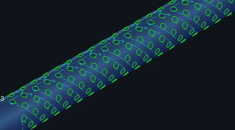
(1) Arc Fly Cutting
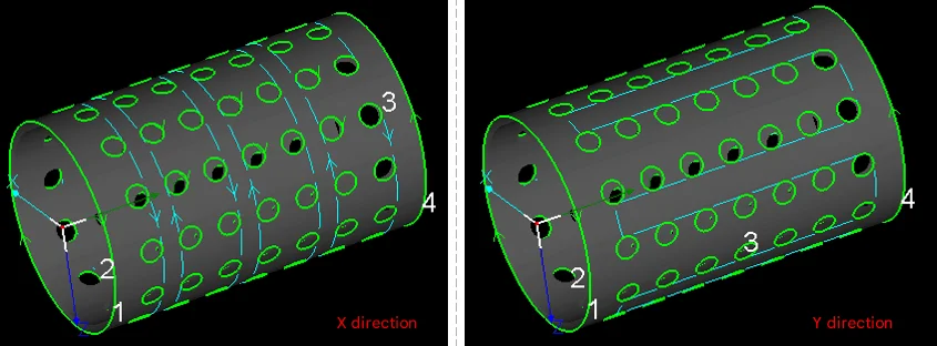
For regularly arranged circular holes, whether on round pipes or rectangular pipes, Arc Fly Cutting should be used.
Maximum distance for flying connection between circles: When the starting point distance between circular holes is less than the set parameter, fly cutting lines can be generated. It is recommended to set this parameter slightly larger than the distance between circular holes.
Sorting direction: The direction of the cutting path for fly cutting determines the cutting sequence of holes.
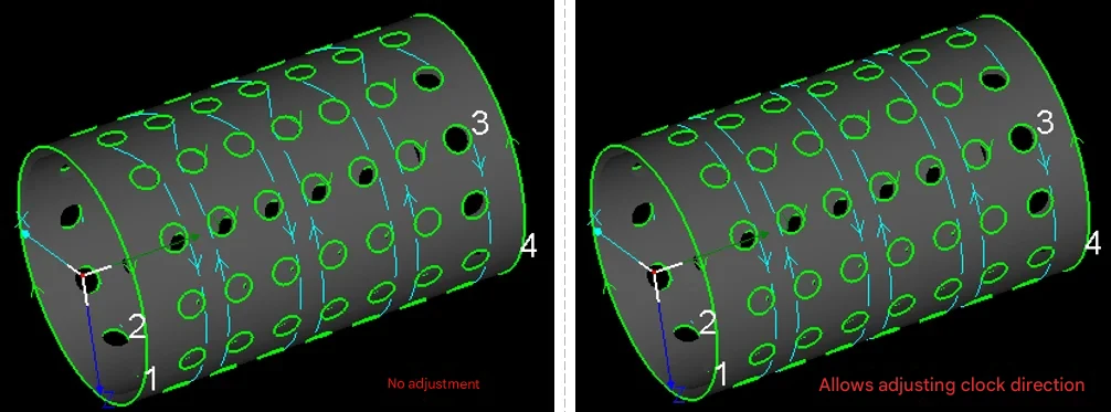
Automatic adjustment of arc clockwise direction: When circular holes have different starting positions and cutting directions, the generated fly cutting lines can be chaotic and the fly cutting trajectory less smooth. Unless there are special requirements, it is recommended to check automatic adjustment. After checking, the software automatically adjusts the cutting direction of each circular hole according to the flying trajectory.
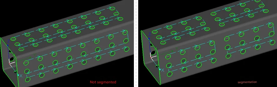
Segmented fly cutting: For long parts, it is recommended to use segmented fly cutting to avoid frequent forward and backward movement of the pipe material over long distances in the Y-axis direction.
For staggered arrangement graphics fly cutting settings:
(2) Linear Fly Cutting
For regularly arranged rectangular or diamond holes without rounded corners, whether on round pipes or rectangular pipes, Linear Fly Cutting should be used.
Allowable distance deviation: When connecting segments on the same straight line with fly cutting lines, segments with distance deviation from the straight line less than this set value will also be planned into this fly cutting path. Default value is 20mm.
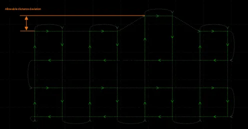
Maximum distance for smooth connection: When switching from one row of fly cutting to another, turning spacing less than this set value can use smooth connection. (It is recommended not to modify this parameter)
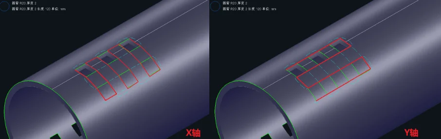
Sorting:
For fly cutting, the default is to cut in the X direction first, then cut in the Y direction after completing the X direction.
During the pipe material clamping and movement process, uncut pipe material may lift in the chuck clamp, or unfallen debris may fall into the chuck interior during clamping, causing damage to the chuck and affecting equipment safety and cutting quality. At this time, the sorting direction of the trajectory can be freely switched.
Segmented fly cutting: For long parts, it is recommended to use segmented fly cutting to avoid frequent forward and backward movement of the pipe material over long distances in the Y-axis direction.
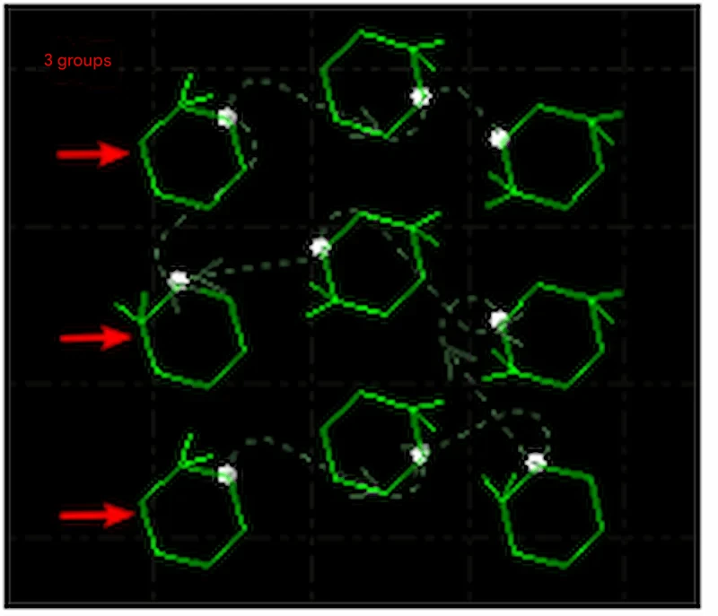
(3) One-Stroke Fly Cutting
One-stroke fly cutting can be used for holes of all shapes, excluding text. It is commonly used for cutting array oval holes, rounded rectangular holes, etc.
Maximum radius of arc fly cutting line: The maximum radius used for fly cutting line direction change transitions, recommended default value is 3mm.
Maximum flying line length: The maximum flying line length supported between two adjacent graphics.
Serpentine sorting: Within the layout area, the cutting path presents a snake-like shape, as shown in the figure below:
Number of groups: The number of grid groups automatically divided for serpentine sorting.
4. What are the Advantages of Laser Fly Cutting?
(1) Significantly Save Time and Improve Work Efficiency
In traditional cutting mode, the cutting head needs to move from one location to another each time, with each movement consuming time. In fly cutting mode, the laser head flies directly to the target position and only starts working when actual cutting is needed. This means the entire cutting process no longer requires frequent stops and positioning, making cutting much faster than traditional methods, especially suitable for some long strip workpieces or high-volume processing requirements.
(2) Significantly Reduce Batch Production Costs
For single large parts, traditional cutting may be more efficient; but when involving more than 50 repeated graphics, fly cutting can save more than 60% of working hours. Longxin Laser uses intelligent nesting AI algorithms to achieve 92% steel utilization rate, significantly reducing batch production costs.
Fly cutting function is not suitable for all cutting tasks. To maximize the benefits of fly cutting function, detailed analysis of the workpiece material, thickness, and processing requirements is needed. For thicker metal materials, fly cutting mode may lead to unstable cutting quality, so it is necessary to choose whether to enable fly cutting function based on different situations. For thin plate materials or thin tubes, the effect of fly cutting is more obvious. It not only reduces wear caused by mechanical movement but also completes a large number of cutting tasks in a short time.
5. How to Use Laser Fly Cutting Function?
(1) Equipment and Material Preparation
Equipment Setup
- Verify that your laser cutting machine is equipped with fly cutting functionality
- Configure machine parameters based on material specifications:
- Adjust laser power according to material thickness
- Set appropriate cutting speed for the material type
- Calibrate the cutting head position
Material Setup
- Securely clamp the workpiece onto the cutting table
- Ensure proper material alignment and positioning
- Verify that the material surface is clean and free of debris
(2) Software Configuration and Programming
Step 1: Create or Import Graphics
- Open your cutting software (e.g., CypCut)
- Draw new graphics or import existing CAD files
- Focus on repetitive patterns such as circles, rectangles, or custom shapes
Step 2: Generate Pattern Arrays
- Select the base graphics that will be repeated
- Use the array function to create multiple copies:
- Set the number of rows and columns needed
- Define spacing between graphics (minimum 1mm to prevent collision)
- Preview the layout to ensure proper distribution
Step 3: Activate Fly Cutting Mode
- Locate the “Fly Cutting” option in the software interface (typically in the upper right corner)
- Select the appropriate fly cutting mode based on your graphics:
- Arc Fly Cutting: For circular holes and curved patterns
- Linear Fly Cutting: For rectangular or square openings
- Racetrack Fly Cutting: For oval or elongated shapes
- One-Stroke Fly Cutting: For complex geometries requiring continuous paths
Step 4: Optimize Cutting Parameters
- Cutting Sequence: Define the order of operations (e.g., left-to-right, top-to-bottom)
- Micro-tab Settings: Configure small connection points (0.1-0.3mm) at start/end positions to prevent part movement during cutting
- Maximum Jump Distance: Set the maximum distance (1-5mm) the laser head can travel between cuts without interrupting the fly cutting sequence
- Precision Control: Adjust recognition deviation to 0.01mm accuracy to minimize path errors
(3) Execute Cutting Operation
Pre-Cutting Checklist
- Review the programmed cutting path and sequence
- Verify all safety systems are operational
- Ensure proper ventilation and fume extraction
During Cutting
- Monitor the cutting process continuously
- Watch for any irregularities in cut quality or machine behavior
- Be prepared to pause or stop the operation if issues arise
(4) Post-Cutting Quality Control
Immediate Inspection
- Examine cut edges for consistency and quality
- Check dimensional accuracy of finished parts
- Verify that all intended cuts were completed
Cleanup and Preparation
- Remove finished parts from the cutting table
- Clear away any cutting debris or slag
- Clean the worktable surface for the next operation
- Store completed parts according to quality standards
6. What are the Application Scenarios for Laser Fly Cutting?
Sheet Metal Dense Hole Processing
- Heat sinks/Filters: Efficiently cut large numbers of regularly arranged circular holes, square holes, or irregular holes, such as server chassis heat dissipation plates and air filter metal meshes. Fly cutting speed is more than 3 times faster than traditional methods.
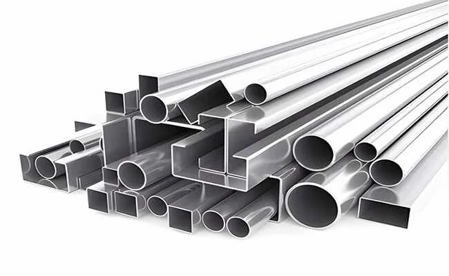
- Architectural Decorative Panels: Hollow carving and railing grids on stainless steel/carbon steel thin plates (≤3mm). Complex patterns can be mass-produced through linear or arc fly cutting.
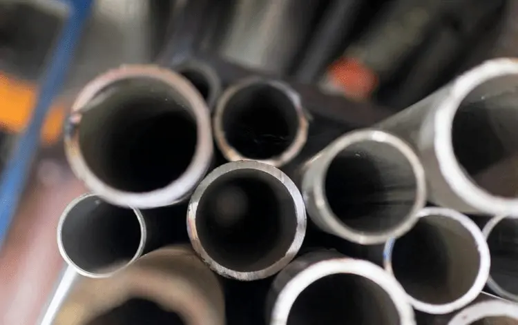
Pipe and Structural Component Processing
- Automotive Exhaust Pipes/Agricultural Machine Brackets: High-speed hole opening or cutting connection parts on round pipes and square pipes. Bond Laser T-series five-axis pipe cutting machines support fully automatic fly cutting for φ20-600mm pipes.
- Elevator Panels/Control Cabinets: Button holes and wire groove opening groups on thin steel plates, using one-stroke fly cutting mode to reduce empty movement paths.
Advertising Signs and Craft Gifts
- Metal Nameplates/Logos: Fine text hollowing on stainless steel or brass thin plates, such as corporate logos and artistic letters.
- Cultural and Creative Products: Laser hollow patterns on greeting cards and bookmarks (such as flowers, geometric patterns), three-dimensional assembly models of acrylic materials.
Consumer Electronics and Home Appliances
- Electrical Enclosure Heat Dissipation Holes: Group circular hole fly cutting on air conditioning panels and power box covers, requiring hole position accuracy of ±0.1mm.
- 3C Components: Mobile phone middle plate positioning holes, headphone metal mesh covers. Han’s Laser ultrafast laser technology achieves micron-level cutting.
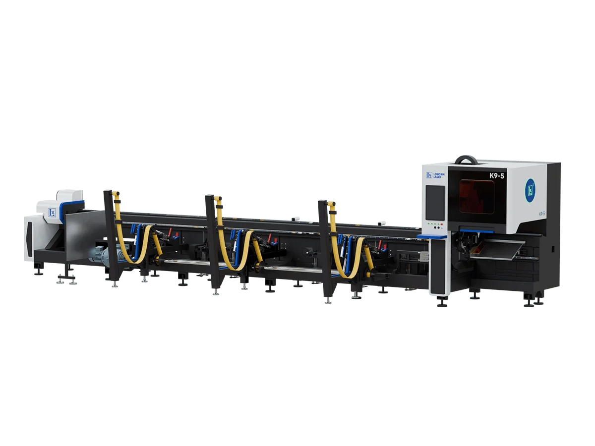
7. Longxin Laser Fly Cutting Solutions
Longxin Laser offers advanced laser tube cutting machines equipped with cutting-edge fly cutting technology. Our machines feature high-performance capabilities with maximum acceleration up to 2.0G, ensuring rapid and precise processing for demanding industrial applications.